
Voltage change generator

A technology of voltage change and generator, which is applied in the direction of measuring electrical variables, components of electrical measuring instruments, instruments, etc. It can solve the problems of large voltage change range, no voltage change test function, and not sine wave.

Inactive Publication Date: 2014-03-26
苏州泰思特电子科技有限公司
View PDF16 Cites 2 Cited by
  • Summary
  • Abstract
  • Description
  • Claims
  • Application Information

AI Technical Summary

Problems solved by technology

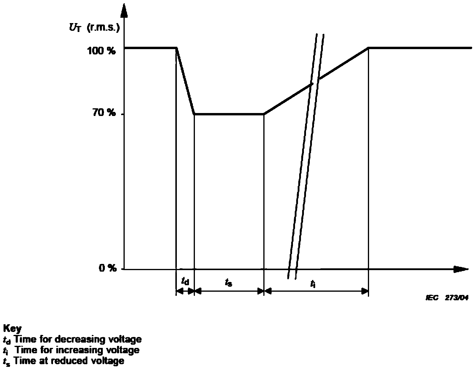
[0008] (2) The voltage change test requires real-time measurement while adjusting the voltage during the ti period to perform closed-loop voltage output control. The voltage change range in the ti stage of the voltage change test is relatively large (70%-100% or greater), and the short time is only 25 (50Hz ) or 30 (60Hz) cycles, which means that the voltage change rate of each AC cycle is above 1%, and the output voltage amplitude is changing in each cycle, which is not a standard sine wave; in addition, when the contact rotates The voltage has jitter. In this case, the real-time accurate measurement of the true RMS value of the AC voltage is a problem.
[0009] Therefore, the usual control methods of measurement, feedback, calculation, and adjustment are faced with the voltage change test. The linearity and voltage regulation accuracy of the voltage increase ti stage cannot meet the standard requirements. The existing GB / T17626.11 / IEC61000-4-11 or GB / T17626.34 / IEC61000-4-34 standard generators mostly include two test functions of voltage sag and short-term interruption, and there is no voltage change test function item, which needs to be improved

Method used


Image

  • Voltage change generator
  • Voltage change generator
  • Voltage change generator

Examples


Embodiment Construction

[0023] The above technical solutions will be further described below in conjunction with specific embodiments. It should be understood that these embodiments are used to illustrate the principle of the present invention rather than limit the protection scope of the present invention.

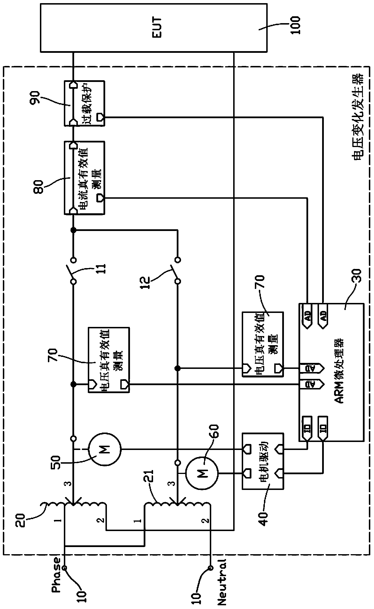
[0024] See image 3 As shown: the voltage change generator of the present invention includes an EUT power supply 10, a first voltage regulator 20, a second voltage regulator 21, a control device 30, a motor drive module 40, a single-phase asynchronous motor 50, a stepping motor 60, Two AC voltage true RMS measurement modules 70 and two semiconductor switches 11 and 12, wherein the EUT power supply 10 is connected to the input terminals of the first voltage regulator 20 and the second voltage regulator 21; the first voltage regulator 20 and the The second voltage regulators 21 are all auto-coupling voltage regulators, and their output ends are respectively connected to the EUT under test 100 thr...


PUM


Abstract

The invention discloses a voltage change generator which comprises an EUT power supply, a first voltage regulator, a second voltage regulator, a control device, a motor drive module, a single-phase asynchronous motor, a step motor, two alternating current voltage true virtual value measurement modules and two switches. The EUT power supply is connected with the input end of the first voltage regulator and the input end of the second voltage regulator, the output end of the first voltage regulator and the output end of the second voltage regulator are respectively in serial connection with an overload protection module through the switches and then are connected with the input end of the EUT power supply, the output end of the control device is connected with the input end of the motor drive module, the two output ends of the motor drive module are connected with the single-phase asynchronous motor and the step motor, the single-phase asynchronous motor is connected with the first voltage regulator, the step motor is connected with the second voltage regulator, and the two alternating current voltage true virtual value measurement modules are connected between the output end of the first voltage regulator and the input end of the control device and between the output end of the second voltage regulator and the input end of the control device respectively. The voltage change generator can effectively solve the problems of linearity and accuracy of output voltage caused by measurement control in the stage that voltage increases by ti.

Description

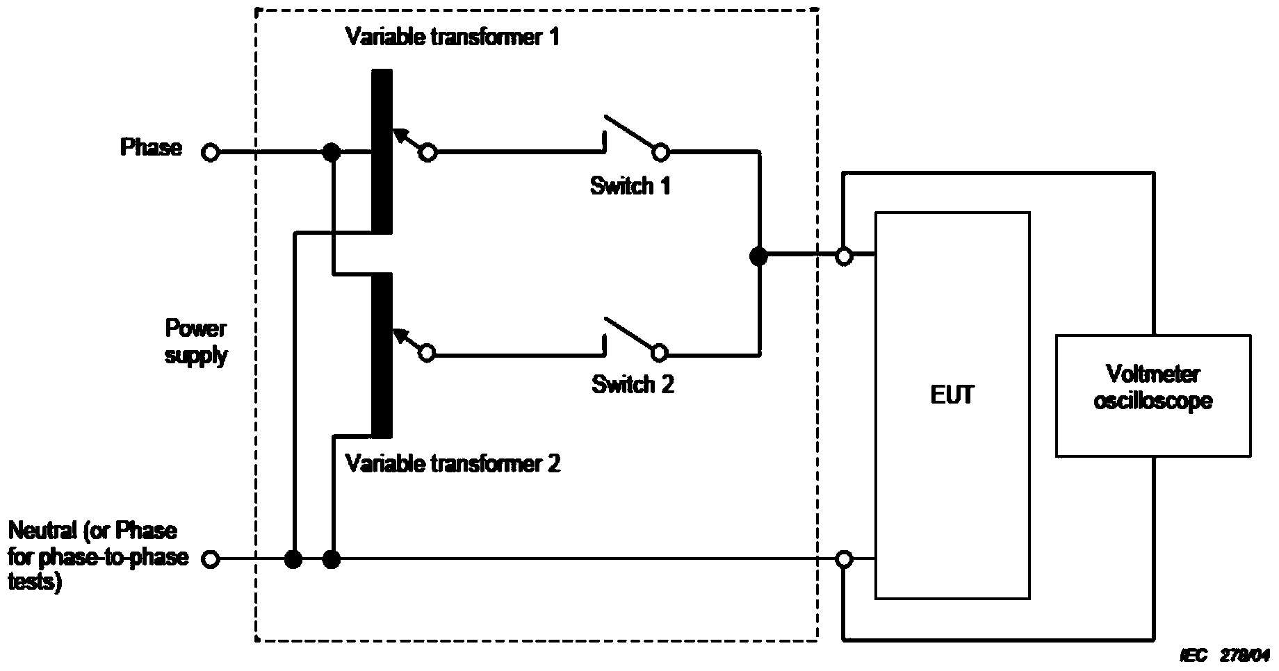
Technical field: [0001] The present invention relates to the technical field of EMC testing, in particular to a voltage used to meet the voltage change EMC test items in GB / T17626.11 / IEC61000-4-11 and GB / T17626.34 / IEC61000-4-34 standards change generator. Background technique: [0002] The currently issued GB / T17626.11 / IEC61000-4-11 and GB / T17626.34 / IEC61000-4-34 standards include three EMC test items: voltage sag, short-time interruption, and voltage change. There are two types of voltage regulation type and transformer voltage regulation type. The principle block diagram of the generator recommended for testing in the standard is as follows: figure 1 As shown, most of the existing generator products use this principle, and their auto-voltage regulators are often equipped with single-phase asynchronous motors to drive tap contacts to adjust the output voltage. For voltage sags and short-term interruptions, the first voltage regulator And the second voltage regulator adjus...

Claims


Application Information

Patent Timeline
IPC IPC(8): G01R1/28
Inventor 黄学军李志刚贾利东胡晖杨伟
Owner 苏州泰思特电子科技有限公司
Learn More