
Optical imaging device, optical system and mobile terminal

An optical imaging and optical system technology, applied in the field of image processing, can solve problems such as difficulty in applying thinner and thinner smartphones, small shaking angles, complex solutions, etc., to achieve improved imaging stability, increased compensation angle, and flexible rotation Effect

Inactive Publication Date: 2014-03-26
YULONG COMPUTER TELECOMM SCI (SHENZHEN) CO LTD
View PDF13 Cites 37 Cited by
  • Summary
  • Abstract
  • Description
  • Claims
  • Application Information

AI Technical Summary

Problems solved by technology

[0007] The above three anti-shake technologies are all suitable for vertical optical lenses, which are difficult to apply to thinner and thinner smartphones; and the scheme is more complicated, and the adjustable shake angle is small

Method used


Image

  • Optical imaging device, optical system and mobile terminal
  • Optical imaging device, optical system and mobile terminal
  • Optical imaging device, optical system and mobile terminal

Examples


Embodiment Construction

[0045]In order to understand the above-mentioned purpose, features and advantages of the present invention more clearly, the present invention will be further described in detail below in conjunction with the accompanying drawings and specific embodiments. It should be noted that, in the case of no conflict, the embodiments of the present application and the features in the embodiments can be combined with each other.

[0046] In the following description, many specific details are set forth in order to fully understand the present invention. However, the present invention can also be implemented in other ways different from those described here. Therefore, the protection scope of the present invention is not limited by the specific details disclosed below. EXAMPLE LIMITATIONS.

[0047] Figure 4 A schematic diagram of an optical imaging device according to an embodiment of the present invention is shown.

[0048] Such as Figure 4 As shown, the optical imaging device accor...


PUM


Abstract

The invention provides an optical imaging system, an optical system and a mobile terminal. The optical imaging system comprises at least one lens system, a reflecting mirror and a driving element. The lens systems are used for projecting images on an imaging element, the reflecting mirror is arranged on a light path between a light inlet of the optical imaging device and the imaging element and reflects light from the light inlet to enable the light to pass through the lens systems, and the driving element is used for fixing the reflecting mirror and driving the reflecting mirror when receiving a control signal from the outside. An optical imaging structure is provided with a horizontal framing light path, and the angle of the reflecting mirror is adjusted to improve imaging stability and extend field of view of framing.

Description

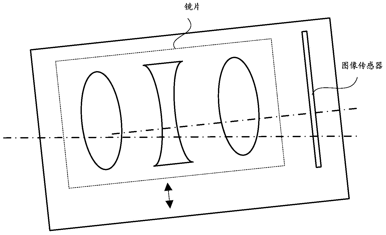
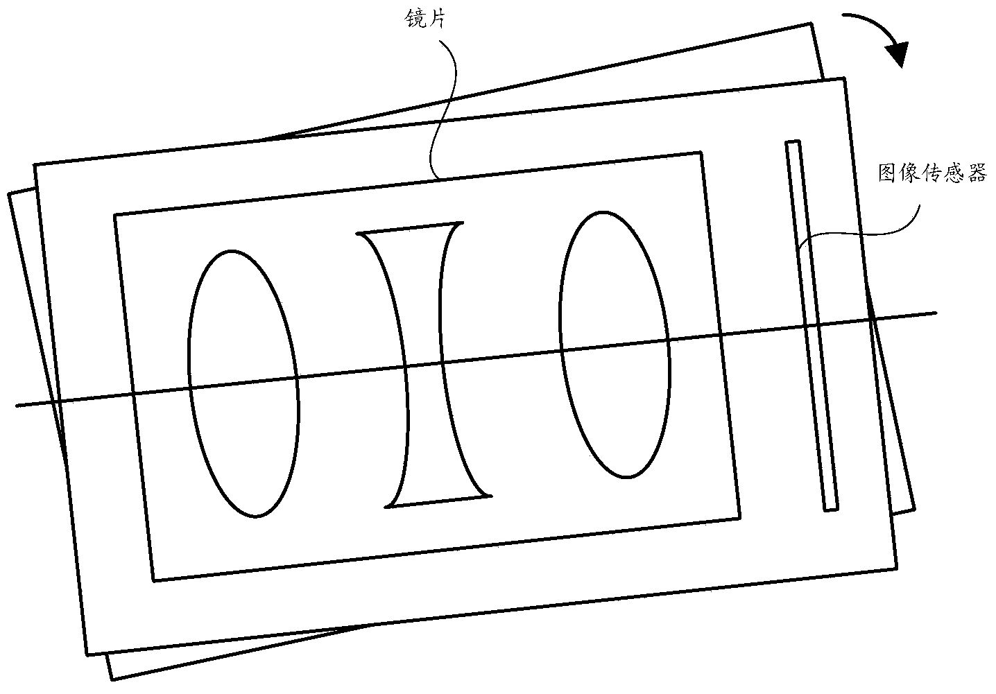
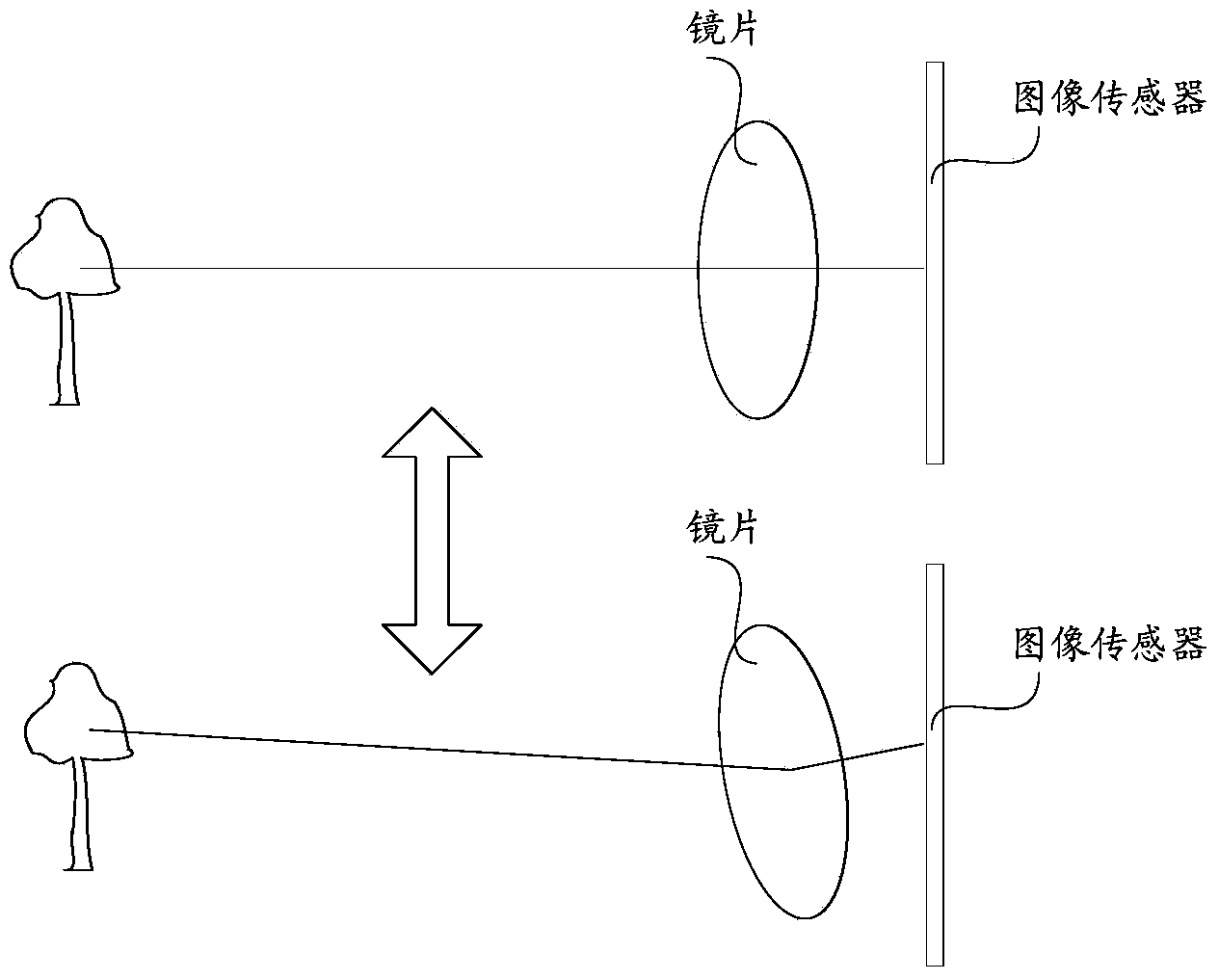
technical field [0001] The present invention relates to the technical field of image processing, in particular to an optical imaging device, an optical system and a mobile terminal. Background technique [0002] Most of current digital cameras, mobile phones and other terminal devices with camera functions support optical image stabilization technology. Optical anti-shake technology is a technology that compensates for the movement of the optical lens or photosensitive element, so that the camera can take clear photos in the case of shaking. [0003] The current optical image stabilization technology mainly has the following three types: [0004] The first type is the movement type of the whole group of lenses, such as figure 1 As shown, the lens and the image sensor are always kept parallel, and the transmission device drives the entire set of lenses to translate and compensate the displacement in the x and y directions, so as to achieve the purpose of anti-shake; [000...

Claims


Application Information

Patent Timeline
Patent Type & Authority Applications(China)
IPC IPC(8): G03B5/00G03B37/00
Inventor 吴炽强
Owner YULONG COMPUTER TELECOMM SCI (SHENZHEN) CO LTD
Learn More