Fuel sipping inspection environmental simulation device

A fuel sipping and environment detection technology, applied in nuclear reactor monitoring, reactors, nuclear power generation, etc., can solve the problem of lack of fuel components, reduced probability of fuel damage, and inability to determine the overall reliability and accuracy of the online fuel sipping detection system and other issues to achieve the effect of reducing the radiation dose and shortening the working time

Active Publication Date: 2014-03-26
STATE NUCLEAR POWER PLANT SERVICE
View PDF4 Cites 9 Cited by
  • Summary
  • Abstract
  • Description
  • Claims
  • Application Information

AI Technical Summary

Problems solved by technology

The current detection sample source acquisition unit 11 is usually completed by actual on-site debugging, but this method will lead to the extension of the entire fuel sipping detection period and increase the radiation risk of the staff
[0007] In addition, due to the continuous improvement of fuel element performance and manufacturing process, the probability of fuel breakage has been greatly reduced, which has led to a serious shortage of fuel assemblies that can be used for detection objects, and during the sipping detection process during refueling overhaul, the overhaul period is limited. The power plant usually cannot provide an additional environment that meets the requirements for testing the function of the detection sample source acquisition unit 11, making it difficult to ensure that the detection sample source acquisition unit 11 can directly meet the detection requirements, thereby affecting the online fuel sipping detection system The comprehensive performance test of the system ultimately leads to the inability to determine the overall reliability and accuracy of the online fuel sipping detection system, which increases the uncertainty of the system and the risk during use
[0008] At present, there has not been a simulated test environment in China that can be used to prove the overall reliability and accuracy of the online fuel sip detection system

Method used


Image

  • Fuel sipping inspection environmental simulation device
  • Fuel sipping inspection environmental simulation device
  • Fuel sipping inspection environmental simulation device

Examples


Embodiment Construction

[0090] The implementation of the present invention will be illustrated by specific specific examples below, and those skilled in the art can easily understand other advantages and effects of the present invention from the contents disclosed in this specification.

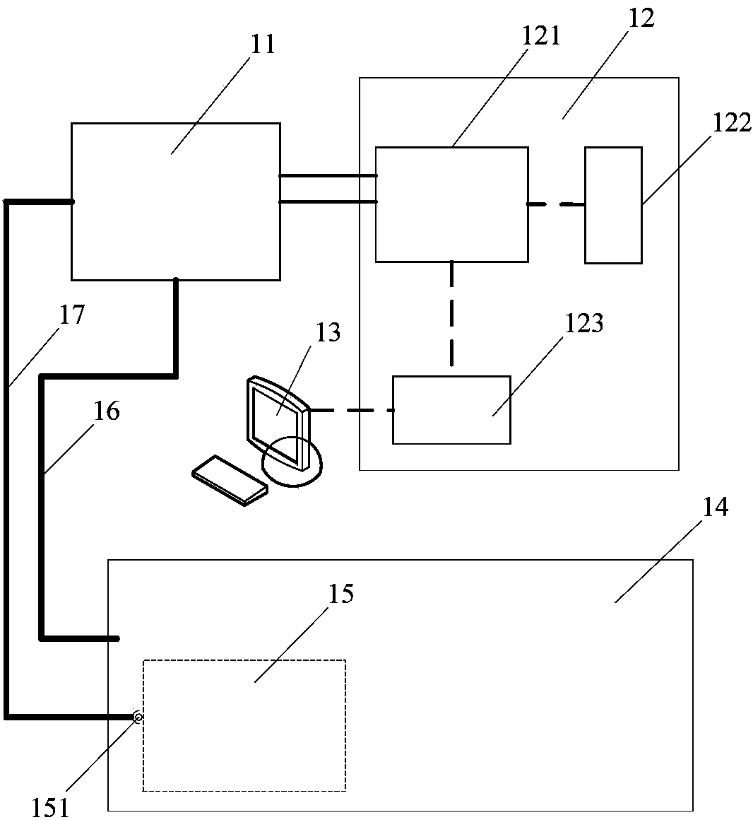
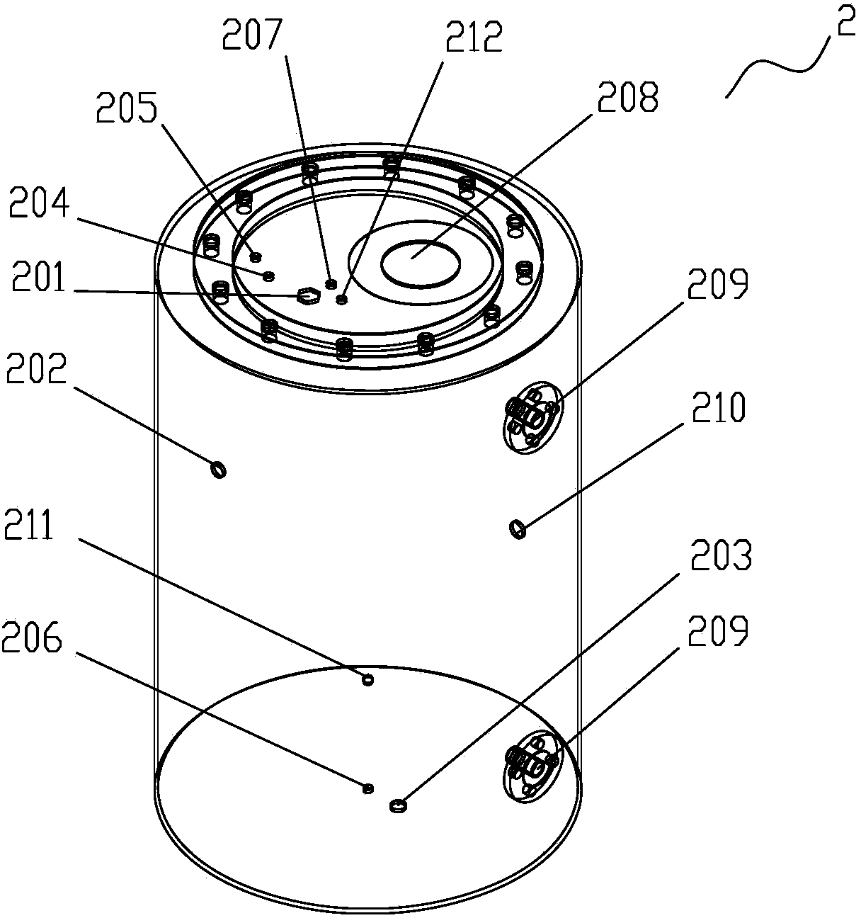
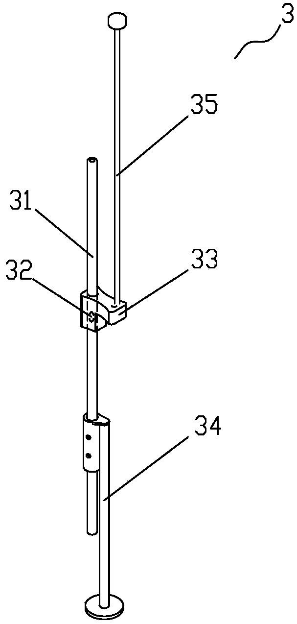
[0091] see Figure 1 to Figure 6 . It should be noted that the structures, proportions, sizes, etc. shown in the drawings attached to this specification are only used to match the content disclosed in the specification, for those who are familiar with this technology to understand and read, and are not used to limit the implementation of the present invention. Limiting conditions, so there is no technical substantive meaning, any modification of structure, change of proportional relationship or adjustment of size, without affecting the effect and purpose of the present invention, should still fall within the scope of the present invention. The disclosed technical content must be within the scope covered. At the sa...


PUM


Abstract

The invention provides a fuel sipping inspection environmental simulation device. The device comprises a closed pressure-bearing water tank, wherein a water absorption connector connected with an on-line fuel sipping inspection system is arranged on the closed pressure-bearing water tank; a simulation defect switching system is mounted in the closed pressure-bearing water tank, and the closed pressure-bearing water tank is also communicated with a water circulating system and a gas circulating system; the simulation defect switching system comprises a hollow simulation defect fuel rod, a simulation defect hole is formed in the circumferential direction of the simulation defect fuel rod, and a simulation defect hole switch is mounted on the simulation defect hole and can open and close the simulation defect hole; a detection sample source injection port is formed in the gas circulating system. The fuel sipping inspection environmental simulation device can effectively test the integral reliability and accuracy of the on-line fuel sipping inspection system and effectively shorten the operation time of a nuclear power site, thereby greatly reducing overhaul windows and dosage of radiation caused to the staff.

Description

technical field [0001] The invention relates to a fuel sipping detection environment simulation device. Background technique [0002] As the energy source of nuclear power plants, fuel is located in the core of the harsh environment. During operation, it is affected by many factors such as radiation, water impact, foreign matter impact, vibration, corrosion, etc., and is prone to radioactive soluble fission products due to damage. Or the leakage of fission gas, affecting the safe operation of the reactor and increasing the probability of public radiation risk. Therefore, in order to ensure the integrity and tightness of the fuel assembly structure and not increase the additional refueling overhaul window, during the refueling overhaul of nuclear power plants, the online fuel sip detection device is usually used to detect the fuel and identify the damaged fuel. And it is isolated and repaired, so as to avoid refilling the damaged fuel into the core, and avoid mixing the dama...

Claims


Application Information

Patent Timeline
IPC IPC(8): G21C17/00
CPCY02E30/30
Inventor 尹绪雨李颖俞照辉谢晨江叶琛
Owner STATE NUCLEAR POWER PLANT SERVICE
Why Eureka
Try Eureka