
Like pole repelling type coreless motor

A technology without iron core and magnetic pole, applied in the direction of magnetic circuit shape/style/structure, etc., which can solve the problems of low magnetic field intensity and complicated magnetic pole manufacturing.

Inactive Publication Date: 2014-03-26
LISHUI VOCATIONAL & TECHN COLLEGE
View PDF0 Cites 0 Cited by
  • Summary
  • Abstract
  • Description
  • Claims
  • Application Information

AI Technical Summary

Problems solved by technology

The common disadvantages of these two structures are that the magnetic poles are complicated to manufacture, and the magnetic field strength is still low, so rare earth permanent magnet materials with extremely strong magnetic properties are required.

Method used


Image

  • Like pole repelling type coreless motor
  • Like pole repelling type coreless motor
  • Like pole repelling type coreless motor

Examples


Embodiment Construction

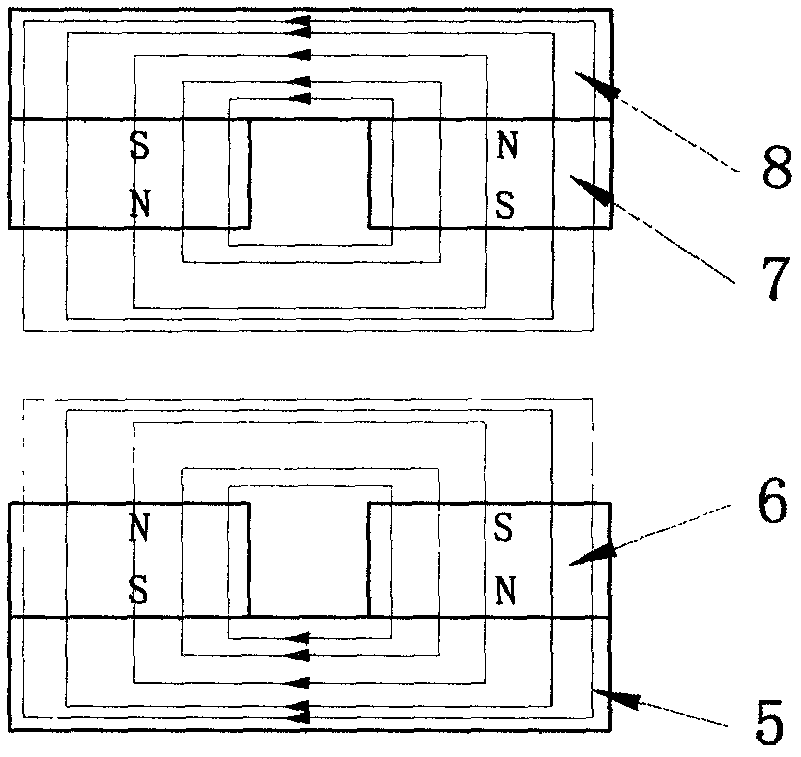
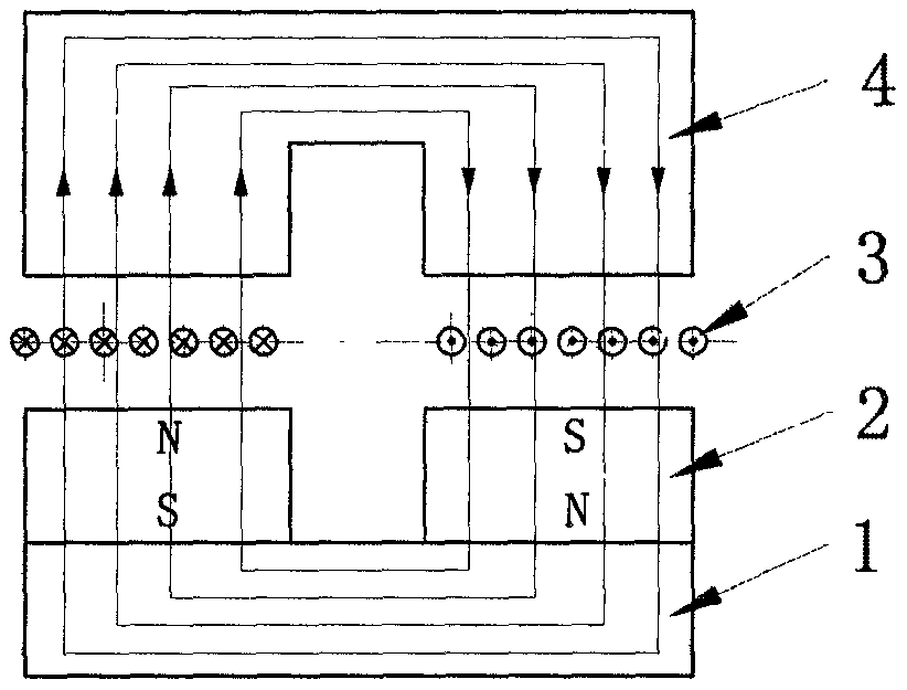
[0012] See attached figure 2 The schematic diagram of the magnetic circuit structure of the present invention, the first magnetic pole group 6 and the second magnetic pole group 7 are placed opposite to each other with same-sex magnetic poles, because the magnetic force lines of the two same-sex magnetic poles repel each other, the magnetic force lines of the magnetic poles are suppressed on the surface of the magnetic poles and concentrated to form a closed loop, and the magnetic energy is relatively concentrated And shorten the length of the magnetic circuit. image 3 It is a schematic diagram of the above-mentioned special example of the motor. In the figure, the armature coil 11 and the armature coil 12 are placed between the two magnetic poles, close to the surface of the first magnetic pole group 6 and the second magnetic pole group 7 respectively. The arrows indicate the direction of armature movement. When the motor When the pivot moves, the coil cuts the magnetic for...


PUM


Abstract

A coreless motor is made by using the principle that like poles repel and opposite poles attract in a magnetic field, wherein the magnetic circuit of the motor is composed of two sets of poles arranged in a manner that like poles are opposite to each other, magnetic field energy is restrained on the surfaces of the poles through the effect that like poles repel, armature coils are placed on the surfaces of the poles, since a magnetic path is arranged in such a way, the distance is short when magnetic lines of force start from an N pole and return to an S pole, and is only equivalent to the length of an air-gap field of a common motor. Therefore, the efficient and coreless motor can be manufactured under a condition of not using a core, the structure is simple, and the manufacturing cost of the like pole repelling type coreless motor is far below that of other similar coreless motors.

Description

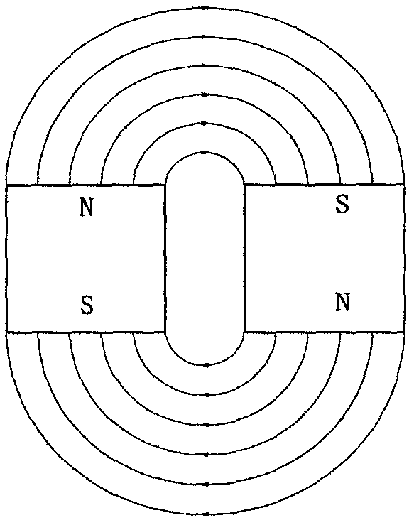
technical field [0001] The invention relates to an iron-core permanent magnet motor, in particular to an iron-core motor with magnetic poles of the same sex repelling each other, which belongs to the field of motors. Background technique [0002] From the basic principles of physics, it can be known that the magnetic force lines of any magnetic field are closed curves, and the magnetic force lines form a closed curve from the N pole to the S pole. figure 1 It is a schematic diagram of the magnetic force lines of two permanent magnets placed adjacent to each other. The magnetic medium in the path that the magnetic field lines pass through in the figure is air. Because the air permeability is extremely low, the magnetic field lines exist in the form of divergence, and the magnetic resistance around the magnetic poles is very large and the magnetic induction intensity is very low. Therefore, in the traditional magnetic circuit design, a medium with high magnetic permeability s...

Claims


Application Information

Patent Timeline
IPC IPC(8): H02K1/06
Inventor 赵洪傅璐璐
Owner LISHUI VOCATIONAL & TECHN COLLEGE
Learn More