
A device for guiding the lattice distribution of magnetic induction intensity

A technology of magnetic induction intensity and lattice, which is applied to the device for guiding the lattice distribution of magnetic induction intensity, and the field of cell microcarriers to construct artificial tissue scaffolds, which can solve the problems of difficult to precisely control the spatial position of cell microcarriers, low efficiency, and difficulty in cell arrangement and positioning, etc. question

Active Publication Date: 2020-03-13
CHONGQING TECH & BUSINESS UNIV
View PDF2 Cites 0 Cited by
  • Summary
  • Abstract
  • Description
  • Claims
  • Application Information

AI Technical Summary

Problems solved by technology

[0007] In view of the existing technology in the process of operating cell microcarriers in a liquid environment to construct artificial tissue scaffolds, direct contact is destructive, low efficiency, cell arrangement and positioning are difficult, and the influence of fluid disturbance makes it difficult to precisely control the spatial position of cell microcarriers, making it difficult to effectively control the space of cell microcarriers. sequence layout and other problems, the purpose of the present invention is to provide a device for guiding the distribution of magnetic induction intensity lattice, the device can resist fluid disturbance, and can precisely control the spatial position of cell microcarriers, so as to realize the active distribution of cell microcarriers in a liquid environment. Arrangement

Method used


Image

  • A device for guiding the lattice distribution of magnetic induction intensity
  • A device for guiding the lattice distribution of magnetic induction intensity

Examples


Embodiment Construction

[0026] The present invention will be described in detail below in conjunction with the accompanying drawings and specific embodiments.

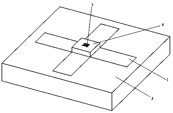
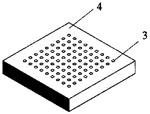
[0027] see figure 1 and figure 2 , it can be seen from the figure that the device for guiding the lattice distribution of magnetic induction intensity in the present invention includes a permanent magnet 1 , a soft magnetic wire 3 and a fixed module 4 . The soft magnetic wires 3 are installed on the surface of the permanent magnet 1 through the fixing module 4 and arranged in an array. Specifically, the fixed module 4 is provided with a number of soft magnetic wire accommodating holes that run through the upper and lower surfaces of the fixed module. In order to make the soft magnetic wires 3 be arranged in an array, correspondingly, the soft magnetic wire accommodating holes are arranged in an array. One-to-one correspondence and installed in each soft magnetic wire housing hole, the depth of the soft magnetic wire housing hole matches th...


PUM

PropertyMeasurementUnit
heightaaaaaaaaaa

Abstract

The invention discloses a device for guiding lattice distribution of magnetic induction intensity. The device comprises a permanent magnet and a plurality of soft magnetic wires arranged in an array mounted on the surface of the permanent magnet by a fixing module; a plurality of soft magnetic wire accommodation holes running through the upper and lower surfaces of the fixing module is arranged inthe fixing module in array, the soft magnetic wires correspond one by one and are mounted in the corresponding soft magnetic wire accommodation holes, and the depth of the soft magnetic wire accommodation hole is matched with the length of the soft magnetic wires; the cross section size of the soft magnetic wire accommodation holes is matched with the cross section size of the soft magnetic wires; the fixing module is mounted on the upper surface of the permanent magnet, the array area corresponding to the soft magnetic wire accommodation holes is located in the weak magnetic field intensityarea of the center of the permanent magnet, and the soft magnetic wires are adsorbed on the surface of the permanent magnet and maintains an upright state under the limit of the soft magnetic wire accommodation holes. By the arrangement, fluid disturbance can be resisted, the spatial position of cell microcarriers can be accurately controlled, and orderly arrangement of the cell microcarriers in liquid environment is realized.

Description

technical field [0001] The invention relates to the technology of constructing artificial tissue scaffolds by using cell microcarriers, in particular to a device for guiding the distribution of magnetic induction intensity in a lattice for assisting in the assembly of magnetic cell microcarriers, and belongs to the technical field of three-dimensional cell assembly in tissue engineering. Background technique [0002] Various unpredictable natural disasters and behavioral accidents are likely to cause tissue damage and organ loss, and the aging and degeneration of tissues and organs also threaten human health. Tissue engineering develops artificial tissues with human organ functions through three-dimensional assembly of cells, which provides a new way for organ repair and regeneration. Human tissue is an ordered structure composed of a variety of cells. How to realize the precise spatial arrangement of different cells is a difficult problem in the development of cell three-di...

Claims


Application Information

Patent Timeline
Patent Type & Authority Patents(China)
IPC IPC(8): C12M1/00C12M1/42
CPCC12M25/14C12M35/06
Inventor 李兴富
Owner CHONGQING TECH & BUSINESS UNIV
Learn More