Low-ripple wave filtering device

A low-ripple and filtering technology, applied in the field of filtering, can solve the problems of lack of DC ripple filtering and need to be improved, and achieve the effect of stable and clear signal, stable signal, and reduction of DC ripple and high-frequency interference.

Inactive Publication Date: 2014-03-26
成都威势科技有限公司
View PDF4 Cites 1 Cited by
  • Summary
  • Abstract
  • Description
  • Claims
  • Application Information

AI Technical Summary

Problems solved by technology

Therefore, it is necessary to filter the transmission signal during transmission. For some transmission signals, the less DC ripple and the fewer high-frequency parts, the more stable the transmission signal is. However, the filtering of DC ripple in the existing filtering is still relatively lacking. ,needs improvement

Method used


Image

  • Low-ripple wave filtering device

Examples


Embodiment

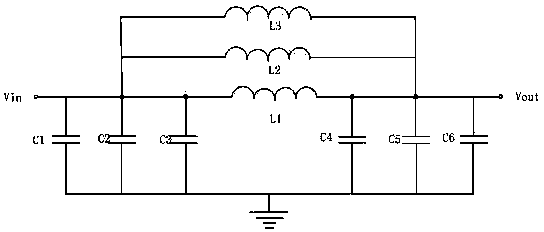
[0014] Such as figure 1 As shown, the present invention comprises electric capacity C1, electric capacity C2, electric capacity C3, electric capacity C4, electric capacity C5, electric capacity C6, inductance L1, inductance L2 and inductance L3, inductance L1, inductance L2 and inductance L3 are equal in size, and the size range of electric capacity C3 is in Between 8-12 microfarads, the capacitor C3 is a ceramic capacitor, the size range of the capacitor C4 is between 4500-5000 microfarads, and the capacitor C4 is an electrolytic capacitor. In this embodiment, the capacitor C3, the inductor L1 and the capacitor C4 are sequentially connected in series to form a closed loop. In this embodiment, the capacitor C2 is connected in parallel to both ends of the capacitor C3, the capacitor C1 is connected in parallel to both ends of the capacitor C2, the capacitor C5 is connected in parallel to both ends of the capacitor C4, and the capacitor C6 is connected in parallel to both ends o...


PUM


Abstract

The invention discloses a low-ripple wave filtering device which comprises a capacitor C1, a capacitor C2, a capacitor C3, a capacitor C4, a capacitor C5, a capacitor C6, an inductor L1, an inductor L2 and an inductor L3. The capacitor C3, the inductor L1 and the capacitor C4 are sequentially serially connected with one another to form a closed circuit; the capacitor C2 is connected to two ends of the capacitor C3 in parallel, the capacitor C1 is connected to two ends of the capacitor C2 in parallel, the capacitor C5 is connected to two ends of the capacitor C4 in parallel, and the capacitor C6 is connected to two ends of the capacitor C5 in parallel; the inductor L2 is connected to two ends of the inductor L1 in parallel, and the inductor L3 is connected to two ends of the inductor L2 in parallel; a common end of the capacitor C1, the capacitor C2, the capacitor C3, the inductor L1, the inductor L2 and the inductor L3 is connected with an input end Vin; a common end of the capacitor C4, the capacitor C5, the capacitor C6, the inductor L1, the inductor L2 and the inductor L3 is connected with an output end Vout. Owing to the principle, the low-ripple wave filtering device has the advantages that direct-current ripple waves in filter signals can be effectively reduced, high-frequency interference can be decreased, and accordingly signals transmitted by microwave circuits are stable.

Description

technical field [0001] The invention relates to the field of filtering, in particular to a device for filtering out low ripples. Background technique [0002] In recent years, my country has successfully developed a point-to-multipoint microwave communication system. Its central station uses an omnidirectional antenna to transmit around. Within 50 kilometers around, there can be multiple points to place user stations. From the user station, multiple telephone lines can be connected separately. to each user. Its overall capacity has different capacities such as 100 lines, 500 lines and 1000 lines. Each user station can be allocated to a dozen or dozens of telephone users, and it can also be extended to users hundreds of kilometers away through relay stations when necessary. . This point-to-multipoint microwave communication system is also very suitable for users in the suburbs of cities, from county towns to rural villages and towns or coastal islands, and for scattered resi...

Claims


Application Information

Patent Timeline
Patent Type & Authority Applications(China)
IPC IPC(8): H03H7/01
Inventor 林海廉保旺
Owner 成都威势科技有限公司
Why Eureka
Try Eureka