
A Phase-stabilized Millimeter Wave Generation System

A technology for phase stabilization and generation of systems, applied in electromagnetic transmitters and other directions, can solve the problems such as the difficulty of the phase compensation range to meet the requirements, the large phase disturbance of the optical fiber link, the increase of system complexity and uncertainty, etc., to overcome the phase compensation range. limited effect

Active Publication Date: 2016-09-07
SHANGHAI JIAOTONG UNIV
View PDF3 Cites 0 Cited by
  • Summary
  • Abstract
  • Description
  • Claims
  • Application Information

AI Technical Summary

Problems solved by technology

However, this optical fiber link phase disturbance acquisition method is after the optical-to-electrical conversion of the optical-carrying millimeter wave, which not only increases the complexity and uncertainty of the system, but also, when the signal frequency is as high as hundreds of GHz, it is difficult for The bandwidth of the system puts forward higher requirements, which is a huge challenge to the current microwave devices. The bandwidth of the existing microwave delay line is difficult to meet such requirements, and the stability of the system is not high enough.
In addition, when the signal frequency is high, the accumulated phase disturbance of the optical fiber link is large, and the phase compensation range of the microwave delay line or the optical fiber delay line is difficult to meet the requirements.

Method used


Image

  • A Phase-stabilized Millimeter Wave Generation System
  • A Phase-stabilized Millimeter Wave Generation System
  • A Phase-stabilized Millimeter Wave Generation System

Examples


Embodiment Construction

[0020] The conception, specific structure and technical effects of the present invention will be further described below in conjunction with the accompanying drawings, so as to fully understand the purpose, features and effects of the present invention.

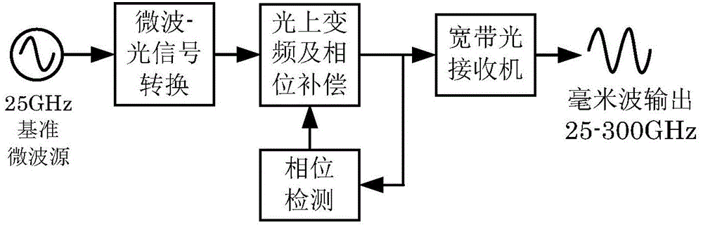
[0021] figure 1 As shown, the structural block diagram of the phase-stabilized millimeter wave generation system provided by the present invention is divided into four modules: a microwave-optical signal conversion module, a photon frequency up-conversion and phase compensation module, a phase detection module, and a broadband optical receiver module.

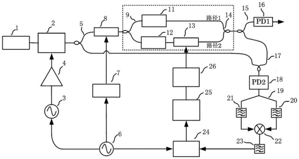
[0022] figure 2 Shown is the electrical connection diagram of an embodiment of the system of the present invention, including: laser 1, optical frequency comb generator 2, 25GHz reference microwave source 3, driver 4, polarization-maintaining fiber coupler (PMC) 5, 10MHz rubidium clock source 6 , phase-locked loop (PLL) 7, first and second acousto-optic frequency shifters (A...


PUM


Abstract

The invention discloses a phase stabilized millimeter wave generating system which comprises a microwave-optical signal conversion module, an optical up-conversion and phase compensation module, a phase detection module and a broadband optical receiver module. The microwave-optical signal conversion module is used for generating optical frequency combs with microwave signal frequency as frequency space, the optical frequency combs are filtered to generate two optical frequency components through the optical up-conversion and phase compensation module, optical fiber link disturbance borne by the two optical frequency components is detected through the phase detection module, the optical up-conversion and phase compensation module is under feedback control, the two optical frequency components pass through the broadband optical receiver module after phase compensation, and phase stabilized millimeter wave signals are obtained by carrying out beat frequency on the two optical signals. According to the phase stabilized millimeter wave generating system, the phase detection method of the optical-carried millimeter waves has nothing to do with the frequency of signals to be detected, and the system can achieve the generation of signals of high phase stability in the range of 25GHz-300GHz.

Description

technical field [0001] The invention relates to a technique for measuring the phase of an optically-carried millimeter-wave signal in the optical domain in the field of microwave photonics, in particular to a millimeter-wave generation system and method for achieving phase stability through optical interference. Background technique [0002] Whether it is in radio-on-fiber (ROF) systems, deep space exploration systems or optical phased array radar systems, the high-stability millimeter-wave source is one of the key components of these systems. There are three main methods for millimeter wave generation: intensity modulation-direct demodulation method, frequency up-conversion method, and optical heterodyne beat frequency method. The optical heterodyne beat frequency method is currently recognized as the most reliable millimeter-wave generation method, which uses two light waves with different frequencies to generate millimeter-wave signals at the beat frequency of the photode...

Claims


Application Information

Patent Timeline
Patent Type & Authority Patents(China)
IPC IPC(8): H04B10/50
Inventor 孙东宁董毅王锶惟
Owner SHANGHAI JIAOTONG UNIV
Learn More