Method, device and system for time synchronization
A time synchronization and time technology, applied in the field of positioning systems, can solve problems such as expensive atomic clocks, cumbersome operations, and GNSS timing receivers that are easily affected by the external environment
- Summary
- Abstract
- Description
- Claims
- Application Information
AI Technical Summary
Problems solved by technology
Method used
Image

Examples
Embodiment 1
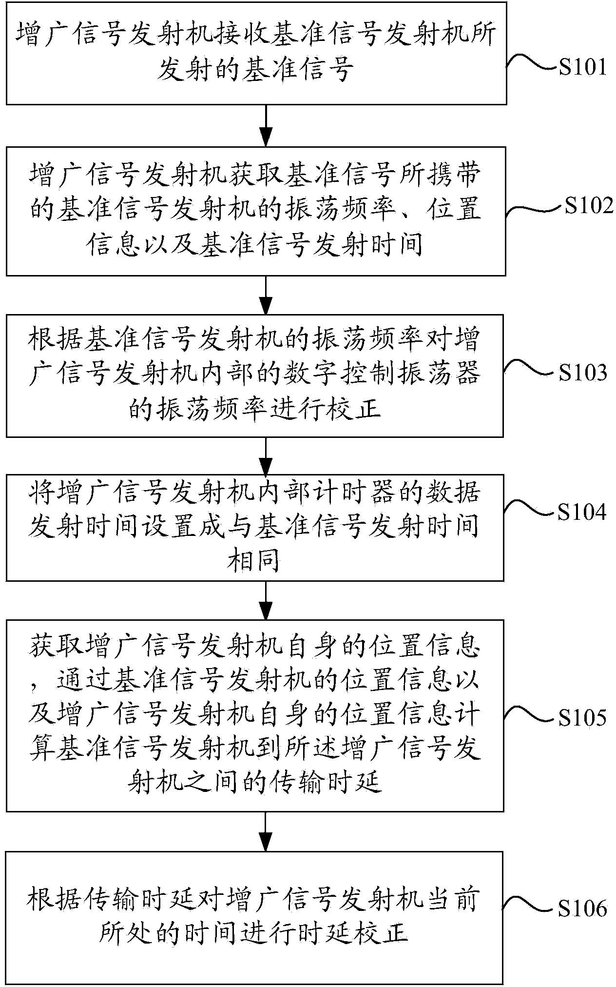
[0054] figure 1 It is a flow chart of a time synchronization method provided in Embodiment 1 of the present application.
[0055] like figure 1 As shown, the method includes:
[0056] S101. The augmented signal transmitter receives the reference signal transmitted by the reference signal transmitter.
[0057] A time synchronization method provided by an embodiment of the present application is applied to a reference signal transmitter and at least one augmented signal transmitter. In the method, the augmented signal transmitter first receives the reference signal transmitted by the reference signal transmitter.
[0058] S102. The augmented signal transmitter acquires the oscillation frequency, location information and reference signal transmission time of the reference signal transmitter carried in the reference signal.
[0059] In this embodiment of the application, the augmented signal transmitter tracks the oscillation frequency of the reference signal transmitter carrie...
Embodiment 2
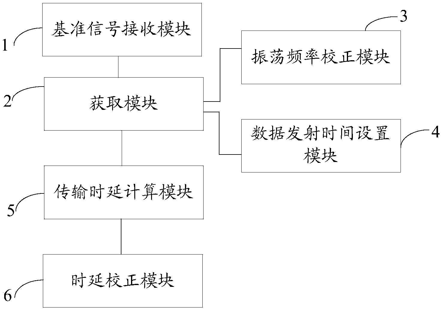
[0071] figure 2 It is a schematic structural diagram of a time synchronization device provided in Embodiment 2 of the present application.
[0072] like figure 2 As shown, the device includes: a reference signal receiving module 1 , an acquisition module 2 , an oscillation frequency correction module 3 , a data transmission time setting module 4 , a transmission delay calculation module 5 and a delay correction module 6 .
[0073] Wherein, the reference signal receiving module 1 is used for receiving the reference signal transmitted by the reference signal transmitter.
[0074] The acquiring module 2 is connected with the reference signal receiving module 1, and is used for acquiring the oscillation frequency, location information and reference signal transmission time of the reference signal transmitter carried by the reference signal.
[0075] The oscillation frequency correction module 3 is connected with the acquisition module 2, and is used for correcting the oscillat...
Embodiment 3
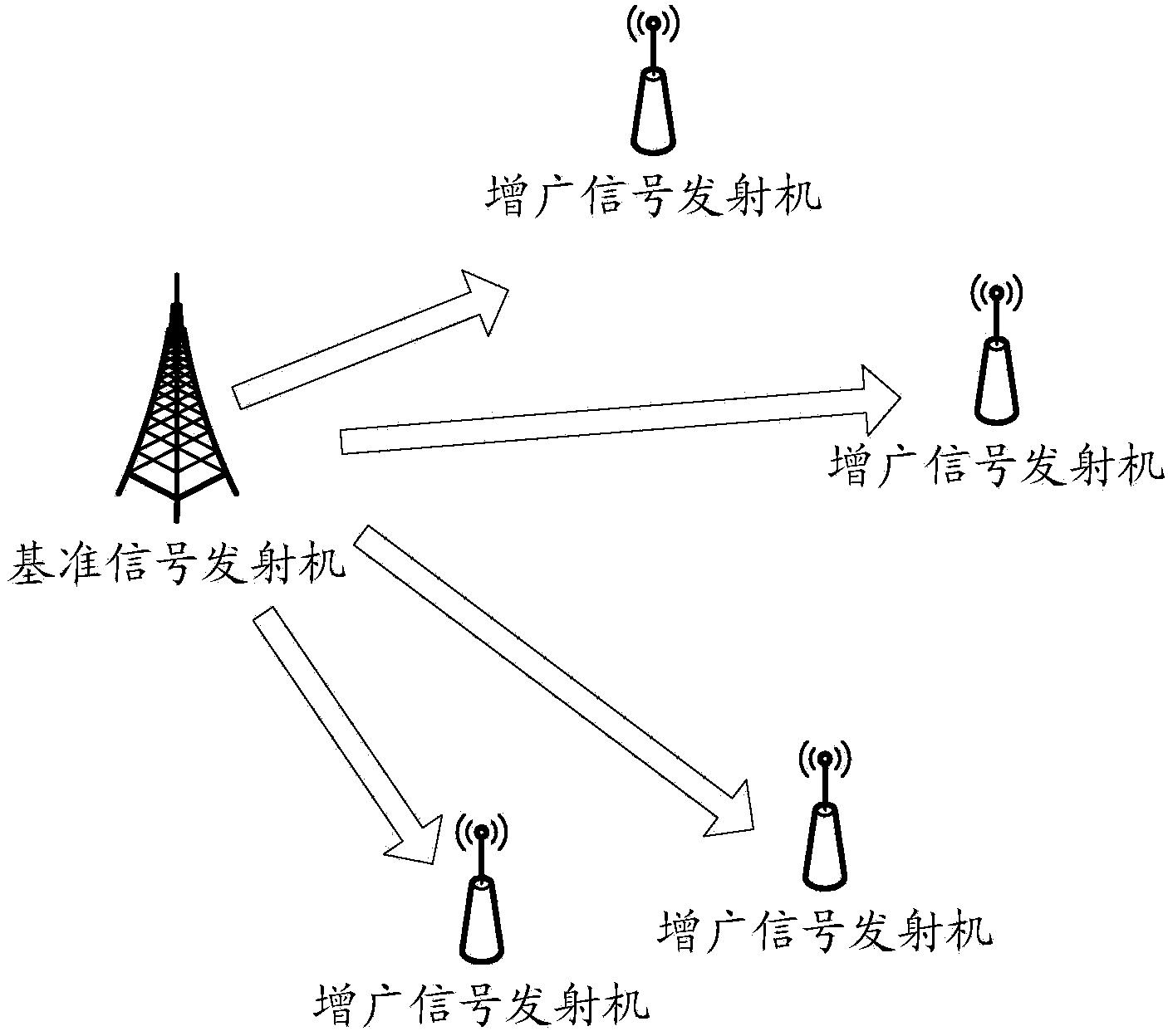
[0086] image 3 It is a schematic structural diagram of a time synchronization system provided in Embodiment 3 of the present application.
[0087] like image 3 As shown, the system includes: a reference signal transmitter and at least one augmented signal transmitter, and the augmented signal transmitter is provided with a time synchronization device as shown in the second embodiment above.
[0088] In the embodiment of the present application, preferably but not limited to, one such as image 3 For the time synchronization system shown, the inventor can also set it as above according to actual needs image 3 The shown at least one time synchronization system communicates by bridging each time synchronization system to form a larger time synchronization system.
[0089] The embodiment of the present application provides a time synchronization system, which includes a reference signal transmitter and at least one augmented signal transmitter. By using the time of a referen...
PUM
 Abstract
Description
Claims
Application Information