
Adaptive filtering separation video decoding device

An adaptive filtering and video decoding technology, applied in the field of video coding, can solve the problems of weakening time correlation, affecting viewing effect, reducing user experience, etc., to achieve the effect of reducing crosstalk, high video definition, and color reproduction without distortion

Inactive Publication Date: 2014-03-26
RES INST OF SUN YAT SEN UNIV & SHENZHEN
View PDF5 Cites 10 Cited by
  • Summary
  • Abstract
  • Description
  • Claims
  • Application Information

AI Technical Summary

Problems solved by technology

[0007] 2. The bright color separation effect of the moving scene in the video image is not ideal, because the time correlation of the spectral characteristics of the moving scene is weakened, and its spatial correlation should be used for brightness separation at this time, but considering that the time correlation increases with the speed of motion The increase gradually weakens, so multi-level processing should be performed on the motion speed, and the time and space separation results are weighted and summed. However, the existing technology does not consider the correlation in the time domain of the video signal, because the separation effect is not ideal.
[0008] 3. The processing of the border and details is the same as that of the static smooth area, so that the high-frequency components in the video signal are lost, affecting the viewing effect and reducing the user experience

Method used


Image

  • Adaptive filtering separation video decoding device
  • Adaptive filtering separation video decoding device
  • Adaptive filtering separation video decoding device

Examples


Embodiment Construction

[0024] The following will clearly and completely describe the technical solutions in the embodiments of the present invention with reference to the accompanying drawings in the embodiments of the present invention. Obviously, the described embodiments are only some, not all, embodiments of the present invention. Based on the embodiments of the present invention, all other embodiments obtained by persons of ordinary skill in the art without creative efforts fall within the protection scope of the present invention.

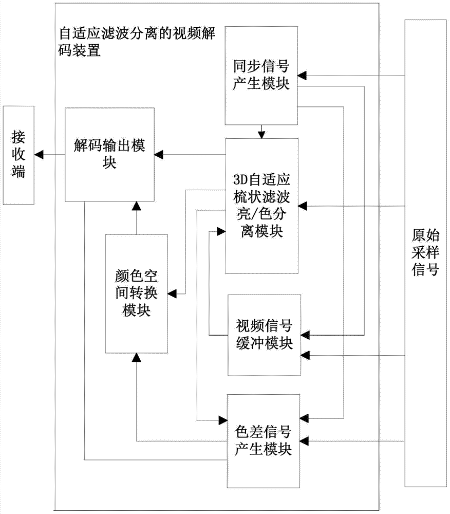
[0025] As described above, the present invention provides a video decoding device for adaptive filtering separation, which can be used according to different contents of the video signal (fast moving picture, slow moving picture, still smooth area, still vertical detail-rich area, Still horizontal detail-rich areas, etc.) adaptively select the appropriate filtering method to achieve high-quality separation of luminance and chrominance of video signals.

[0026] Spe...


PUM


Abstract

The invention discloses an adaptive filtering separation video decoding device. The adaptive filtering separation video decoding device comprises a synchronous signal generation module used for analyzing received original sampling signals and generating synchronous signals, a 3D self-adaptive comb-shaped filtering brightness / color separation module, a color difference signal generation module, a video signal buffering module, a color space conversion module and a decoding output module, wherein the 3D self-adaptive comb-shaped filtering brightness / color separation module is used for converting the sampling signals into a current frame image, processing the current frame image, a brightness chroma image and a frame difference motion image, and separating brightness signals from chroma signals, the color difference signal generation module is used for generating two color difference signals, the video signal buffering module is used for storing video signals and providing the brightness chroma image and the frame difference motion image, the color space conversion module is used for converting the received signals into RGB signals, and the decoding output module is used for combining and outputting a YUV mage and an RGB image. The adaptive filtering separation video decoding device takes the video signal space and time correlation into account, and automatically selects the best scheme according to the motion information of the video signals, is ideal in brightness and chroma separation effect of the video signals, and improves user experience.

Description

technical field [0001] The invention relates to the field of video coding, in particular to a video decoding device for adaptive filtering and separation. Background technique [0002] At present, the world's three major TVs are NTSC (National Television Standards Committee, the National Television Standards Committee of the United States), PAL (Phase Alteration Line, progressive phase inversion), and SECAM (Sequentiel Couleur A Memoire, which transmits color and storage in sequence). Standard is the system for analog processing and transmission of analog TV signals. In order to save transmission bandwidth, the red (R), green (G), and blue (B) analog TV signals first form a luminance signal Y and two color difference signals U and V, and then make the color difference signal modulate a certain load wave, after modulation The chrominance signal is then mixed with the luminance signal to become a full TV signal for transmission. In order to obtain the decoded video signal at...

Claims


Application Information

Patent Timeline
Patent Type & Authority Applications(China)
IPC IPC(8): H04N19/117H04N19/44H04N9/78
Inventor 罗笑南胡宇辉刘海亮杨艾琳苏航
Owner RES INST OF SUN YAT SEN UNIV & SHENZHEN
Learn More