Plasma flat light source driving method

A flat-panel light source and plasma technology, which can be applied to light sources, electric light sources, lighting devices, etc., can solve the problems of uneven lighting, environmental pollution, and low luminous efficiency, and achieve the effects of reducing power consumption and improving luminous efficiency.

Inactive Publication Date: 2014-03-26
NANJING JIANQIAO XINGANG TECH DEV CO LTD
View PDF2 Cites 0 Cited by
  • Summary
  • Abstract
  • Description
  • Claims
  • Application Information

AI Technical Summary

Problems solved by technology

[0002] The current mature product of the light source using the principle of plasma discharge is tubular fluorescent lamp, which is divided into cold cathode fluorescent lamp and hot cathode fluorescent lamp. uniform
For flat fluorescent lamps, inert gas is used as the working gas, which avoids the problem of environmental pollution and has good uniformity, but the luminous efficiency is not high, and needs to be improved from various technical links

Method used


Image

  • Plasma flat light source driving method
  • Plasma flat light source driving method
  • Plasma flat light source driving method

Examples


Embodiment Construction

[0018] The present invention will be further explained below in conjunction with the drawings.

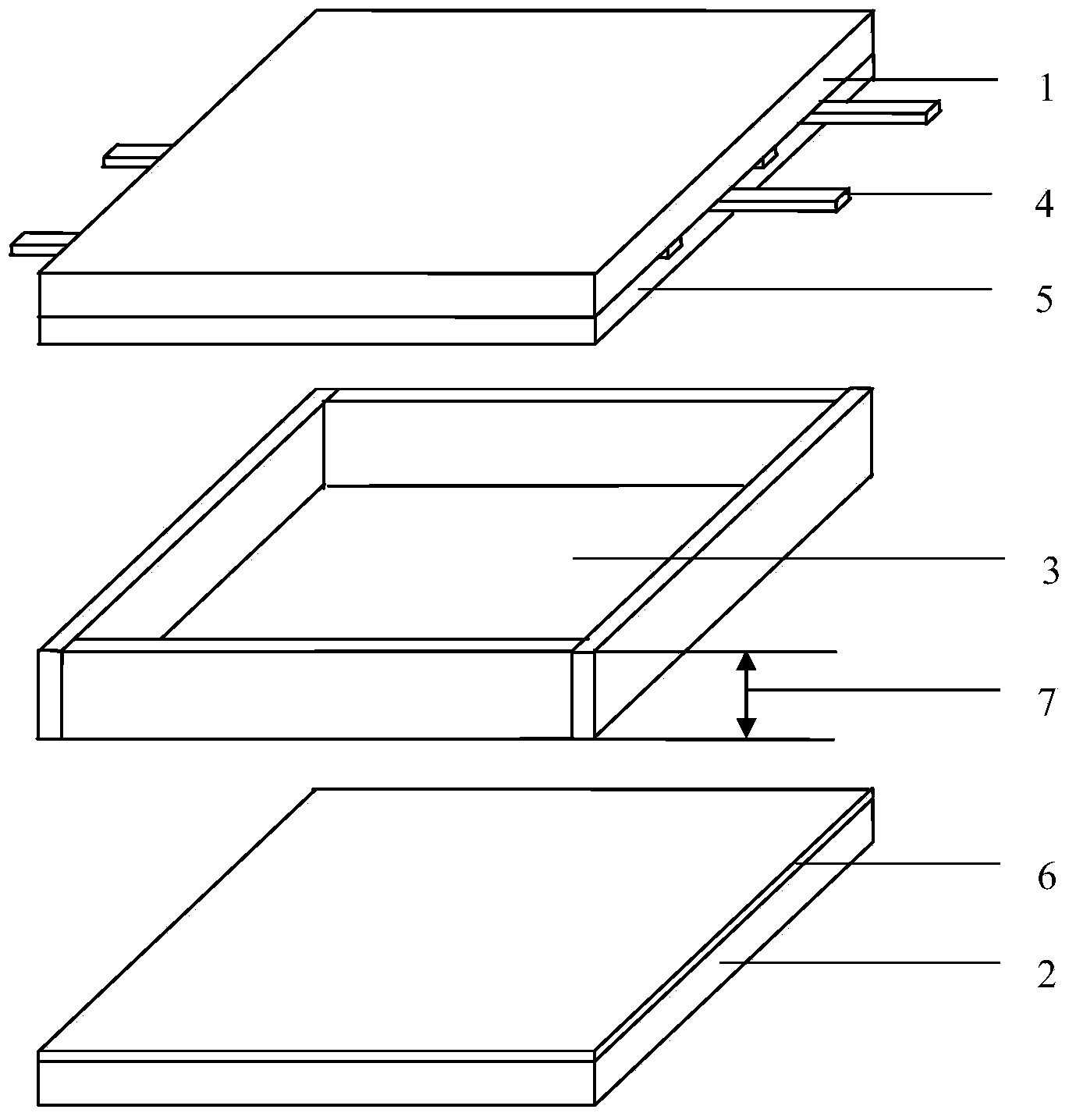
[0019] Such as figure 1 As shown, a preferred plasma flat light source of the present invention includes a front substrate 1, a rear substrate 2, and a discharge cavity 3. The discharge cavity 3 is arranged between the front substrate 1 and the rear substrate 2, and the front substrate 1 is close to one side of the discharge cavity. A transparent medium layer and a protective film 5 are arranged on the side, and a number of parallel electrodes 4 driven by square wave pulses are arranged between the front substrate 1 and the transparent medium layer and the protective film 5; the back substrate 2 is coated with three parallel electrodes on the side close to the discharge cavity 3 Mixing layer of color phosphor 6.

[0020] The distance between two adjacent parallel electrodes of this type of plasma flat light source is greater than or equal to 3 mm.

[0021] The discharge cavity of this ty...


PUM


Abstract

The invention discloses a plasma flat light source driving method. A driving signal applied to a plasma flat light source adopts a periodic signal formed by N square-wave pulses which are provided with rapid rising edges and rapid falling edges with frequency of 10-80KHZ and M low-level signals in a spacing way. The square-wave pulses are provided with the rapid rising edges and the falling edges. The plasma flat light source discharges only at the rising edges and the falling edges of the square-wave pulses and does not discharge at low levels. N is less than 5, M is less than 5 and N is greater than or equal to M. In order to improve light emission efficiency of the plasma flat light source, the invention brings forward the driving waveform adopting the mode that multiple high-level square-wave pulses and the low-level signals are arranged in the spacing way under the premise that the square-wave pulses are provided with steep rising edges so that the plasma flat light source can discharge intermittently and can emit light normally. Therefore, discharging maintenance time is reduced, electric heat loss can be greatly reduced, heat amount of a screen is reduced and light emission efficiency of the plasma flat light source is enhanced.

Description

Technical field [0001] The present invention relates to the technical field of plasma flat panel light sources, in particular to a driving method of plasma flat panel light sources with improved luminous efficiency. Background technique [0002] The light source that adopts the principle of plasma discharge is currently a tube-shaped fluorescent lamp, which is divided into cold cathode fluorescent lamp and hot cathode fluorescent lamp. This kind of light source has high luminous efficiency, but because mercury vapor is used as the working gas, it pollutes the environment and does not emit light. Evenly. For flat fluorescent lamps, inert gas is used as the working gas to avoid the problem of environmental pollution, and the uniformity is good, but the luminous efficiency is not high, and it needs to be improved from various technical links. Summary of the invention [0003] In order to overcome the shortcomings in the prior art, the present invention provides a method for driving ...

Claims


Application Information

Patent Timeline
Patent Type & Authority Applications(China)
IPC IPC(8): H05B41/30
Inventor 曾倩倩匡文剑胡凯李青
Owner NANJING JIANQIAO XINGANG TECH DEV CO LTD
Why Eureka
Try Eureka