Backlight module and liquid crystal display module

A backlight module, light guide plate technology, applied in optics, nonlinear optics, instruments, etc., can solve problems such as LED temperature rise, and achieve the effect of simple structure

Active Publication Date: 2017-04-26
TCL CHINA STAR OPTOELECTRONICS TECH CO LTD
View PDF9 Cites 2 Cited by
  • Summary
  • Abstract
  • Description
  • Claims
  • Application Information

AI Technical Summary

Problems solved by technology

This requires a high current drive for the LED, resulting in a sharp rise in the temperature of the LED

Method used


Image

  • Backlight module and liquid crystal display module
  • Backlight module and liquid crystal display module
  • Backlight module and liquid crystal display module

Examples


Embodiment Construction

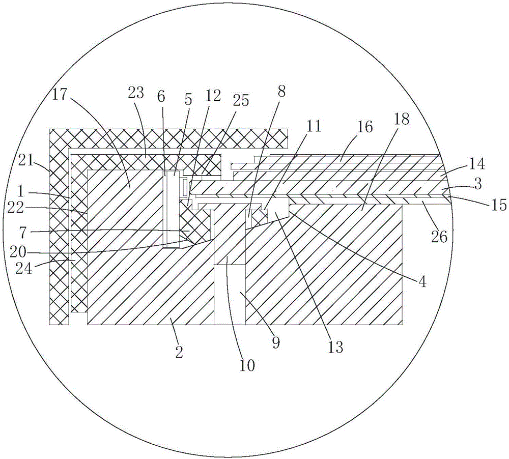
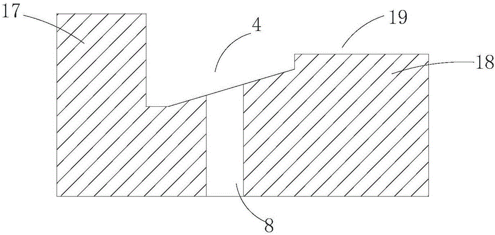
[0018] The present invention will be described in further detail below in conjunction with the accompanying drawings and embodiments.

[0019] Such as figure 1 with figure 2 As shown, a backlight module of the present invention includes a middle frame 1, the middle frame 1 is L-shaped, from figure 1 It can be seen from the figure that it rotates 180 degrees clockwise. The middle frame 1 has a parallel portion 23 parallel to the surface of the light guide plate 3 and a vertical portion 24 perpendicular to the parallel portion 23. An accommodation portion 22 is formed between the parallel portion 23 and the vertical portion 24. The heat sink 2 is set in the housing portion 22, and the heat sink 2 carries the optical film 14, the light guide plate 3, the reflection sheet 15 and the back plate 26, and the side of the light guide plate 3 opposite to the heat sink 2 extends to the heat sink 2 Between the parallel part 23 of the middle frame 1, a liquid crystal panel 16 is carried...


PUM


Abstract

The invention provides a backlight module which comprises a middle frame, a light bar, a heat sink and a light guide plate, wherein the heat sink is arranged in the middle frame; the light guide plate is arranged on the heat sink; a groove is formed at the position of the light bar on the heat sink; the light bar is arranged on a groove wall of a side edge, opposite to the light bar, of the groove and the light guide plate; the beads of the light bar and the side edge of the light guide plate are oppositely arranged; a heat-conducting medium is filled between the light bar and the groove wall of the groove; and a pressing block is arranged in the groove; the light bar, the heat-conducting medium and the groove wall of the groove are tightly clung to each other. The invention also provides a liquid crystal display module which comprises the backlight module. Compared with the prior art, the backlight module has the advantages that the pressing block is arranged in the groove of the heat sink and is used for fixing the light bar so that the fixing of the light bar is realized, the structure is simple and the luminance of the light bar is not influenced.

Description

technical field [0001] The invention relates to a liquid crystal panel module technology, in particular to a backlight module and a liquid crystal display module. Background technique [0002] At present, due to the resolution of liquid crystal display modules and HDR (High-Dynamic Range) technology, the brightness requirements for backlight components are getting higher and higher. For example, the application of HDR technology requires brightness to be above 1000 nits. This requires a high current drive for the LED, resulting in a sharp rise in the temperature of the LED. In order to improve the heat dissipation efficiency of LEDs, thermal paste is used instead of heat-conducting glue as the heat-conducting contact between the light bar and the heat sink. However, the heat-conducting glue itself is not sticky. How to fix the light bar on the heat sink without affecting the brightness of the light bar becomes a problem. issues that need resolving. Contents of the inventi...

Claims


Application Information

Patent Timeline
IPC IPC(8): G02F1/13357
CPCG02F1/133603G02F1/133608G02F1/133628
Inventor 李德华阙成文萧宇均
Owner TCL CHINA STAR OPTOELECTRONICS TECH CO LTD
Why Eureka
Try Eureka