Eliminating and transferring device for voltage-withstanding test of electric heating tube shrinking machine and test method

A technology of withstand voltage test and transfer device, applied in the direction of using stable tension/pressure test material strength, electrical program control, program control in sequence/logic controller, etc. Equipment, high energy consumption and other problems, to achieve the effect of omitting manual reset, reliable working process and high degree of automation

Inactive Publication Date: 2014-04-02
宋书兴
View PDF5 Cites 21 Cited by
  • Summary
  • Abstract
  • Description
  • Claims
  • Application Information

AI Technical Summary

Problems solved by technology

In the prior art, the withstand voltage test generally needs to be performed manually by the operator. Although this method is simple and easy, manual operation is prone to errors, and because the test voltage of the withstand voltage test is relatively high, it is prone to danger.
In the tube shrinking process, due to the irregular manual operation, there are often problems such as rear-end collision of the electric heating tube, damage to the tube shrinking equipment, defective products, high energy consumption, and low efficiency.
Paid the price of wasted energy and inefficiency

Method used


Image

  • Eliminating and transferring device for voltage-withstanding test of electric heating tube shrinking machine and test method
  • Eliminating and transferring device for voltage-withstanding test of electric heating tube shrinking machine and test method
  • Eliminating and transferring device for voltage-withstanding test of electric heating tube shrinking machine and test method

Examples


Embodiment Construction

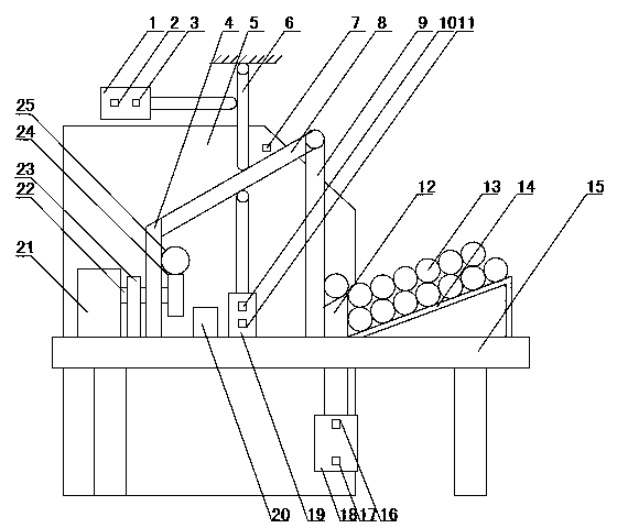
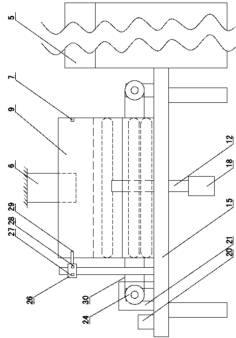
[0047] Figure 1~5 It is the best embodiment of the present invention, below in conjunction with attached Figure 1~5 The present invention is described further:

[0048] Such as Figure 1~2As shown, the pressure test removal transfer device and test method of the electric heating tube shrinking machine of the present invention include five parts: an electric heating tube storage mechanism, a single tube separation mechanism, a pressure testing mechanism, a rejection transmission mechanism and a shrinking mechanism, wherein the electric heating tube The storage mechanism is set at the front end of the workbench 15, the single-tube separation mechanism is located under the workbench 15, passes through the workbench 15 from bottom to top, and is located behind the electric heating tube storage mechanism, and the rejecting transmission mechanism is set at the single-tube separation mechanism In the rear, the pressure test mechanism is fixed on the left side of the rejecting tra...


PUM


Abstract

The invention discloses an eliminating and transferring device for a voltage-withstanding test of an electric heating tube shrinking machine and a test method, belonging to the field of electric heating tube machining devices. The eliminating and transferring device for the voltage-withstanding test of the electric heating tube shrinking machine comprises a work table (15), wherein an electric heating tube storage mechanism for an electric heating tube (13) to be tested is arranged at the front end of the work table (15); a single tube separation mechanism is vertically arranged on the back of the electric heating tube storage mechanism and fixed under the work table (15); an eliminating and transferring mechanism is positioned at the back of the single tube separation mechanism; a voltage testing mechanism, used for the voltage withstanding test of the electric heating tube (13), is horizontally arranged on the left side of the eliminating and transferring mechanism; the single tube separation mechanism, the voltage-withstanding test mechanism and the eliminating and transferring mechanism are controlled through a PLC (Programmable Logic Controller). According to the eliminating and transferring device for the voltage-withstanding test of the electric heating tube shrinking machine and the test method, the voltage-withstanding test is performed automatically on front of the electric heating tube shrinking machine; the electric heating tubes meeting the voltage-withstanding test are fed into the tube shrinking machine automatically; the unqualified electric heating tubes are eliminated.

Description

technical field [0001] The invention discloses a withstand voltage test rejecting transfer device and a test method of an electric heating tube shrinking machine, which belong to the field of electric heating tube processing equipment. Specifically, it relates to a device for automatically performing a withstand voltage test before the electric heating tube shrinks, automatically rejects the electric heating tubes that do not meet the test requirements, and at the same time automatically sends the electric heating tubes that meet the test requirements into the tube shrinking machine. Background technique [0002] In the current production process of electric heating tubes, the conductive rod is first put into the metal casing, and then the insulating medium is put into the conductive rod and the metal casing, and then put into the shrinking machine for shrinking operation. Before shrinking the tube, it is generally necessary to use a voltage tester to perform a withstand vol...

Claims


Application Information

Patent Timeline
Patent Type & Authority Applications(China)
IPC IPC(8): B07C5/34G01N3/12G05B19/05
Inventor 宋书兴孙亚灿严纪兰
Owner 宋书兴
Why Eureka
Try Eureka