Large internal high-pressure forming die

An internal high-pressure forming and mold technology, applied in the field of large-scale internal high-pressure forming molds, can solve the problems of prolonging the time of liquid filling and exhausting, increasing the volume of compressed liquid, and prolonging the cycle of pressurization, so as to reduce the volume and shorten the time, the effect of improving production efficiency

Inactive Publication Date: 2014-04-02
DALIAN DESIGN INST CO LTD CHINA FIRST HEAVY IND +1
View PDF6 Cites 7 Cited by
  • Summary
  • Abstract
  • Description
  • Claims
  • Application Information

AI Technical Summary

Problems solved by technology

This creates two problems. One is that the low-pressure pipeline and the high-pressure pipeline filled with liquid and exhaust are connected. Since the forming pressure of common cars can generally reach 200-300MPa, the compression rate of high-pressure water can reach more than 10%, which increases The volume of the liquid that needs to be compressed prolongs the period of pressurization, and at the same time, a larger volume of the supercharger is required to meet the requirements; the second is that the sealing punch is limited by the size of the tube billet, and at the same time, in order to reduce the volume of the supercharger , the diameter of the internal channel should not be too large, which makes it difficult to quickly fill and exhaust parts with a large volume due to the influence of the channel diameter during liquid filling and exhausting, prolonging the time of liquid filling and exhausting , thus greatly reducing the production efficiency

Method used


Image

  • Large internal high-pressure forming die
  • Large internal high-pressure forming die

Examples


Embodiment Construction

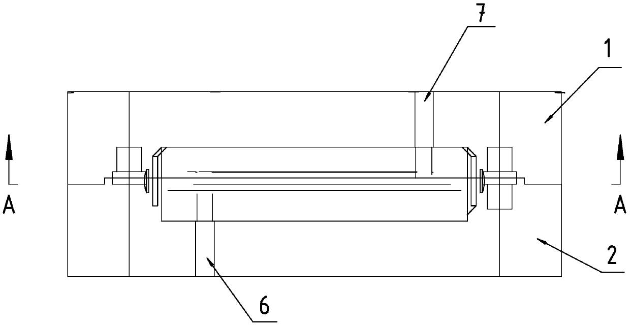
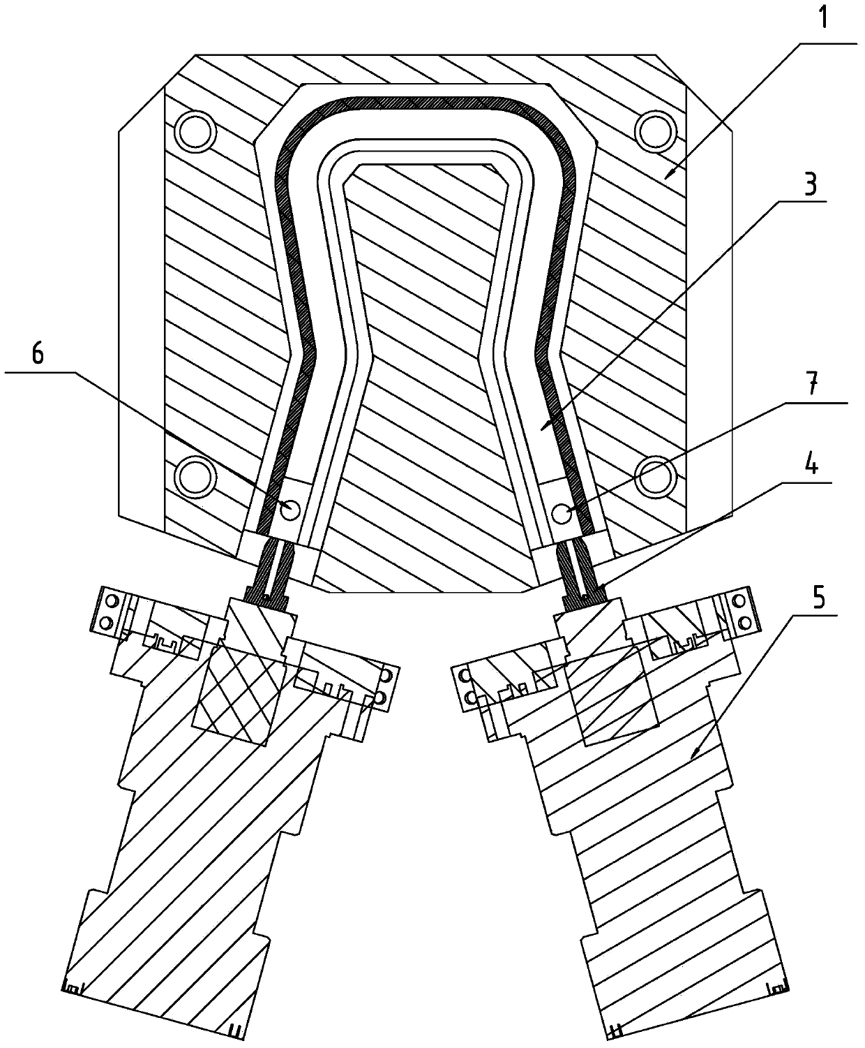
[0014] The present invention will be further described below in conjunction with the accompanying drawings. Such as Figure 1-2 As shown, a large-scale internal high pressure forming die includes an upper die 1, a lower die 2, two sealing punches 4, two side thrust cylinders 5, an inlet pipe 6 and an outlet pipe 7, and the upper die 1 and the lower die After the mold 2 is closed, the cavity of the part is formed. The two sealing punches 4 are installed on the two side push cylinders 5 respectively, and are driven by the side push cylinder 5 to enter the tube blank to complete the end sealing. The water inlet pipe 6 is set in the lower mold 2 , The outlet pipe 7 is arranged in the upper mold 1 .

[0015] The diameter of the water inlet pipe 6 of the present invention is 1.1-1.4 times of the diameter of the pipe material 3, and the diameter of the outlet pipe 7 is 0.8-0.9 times of the diameter of the pipe material 3; They are connected by a high-pressure water pipe. The diamet...


PUM

PropertyMeasurementUnit
Diameteraaaaaaaaaa

Abstract

The invention discloses a large internal high-pressure forming die which comprises an upper die, a lower die, two sealing punches, two side pushing cylinders, a water incoming pipe and a water outgoing pipe. A cavity of parts is formed after the upper die and the lower die are assembled, the sealing punches are mounted on the side pushing cylinders respectively and driven by the side pushing cylinders to enter a pipe blank to complete end portion sealing, the water incoming pipe is arranged in the lower die, and the water outgoing pipe is arranged in the upper die. The water incoming pipe is arranged in the lower die, so that quick liquid filling can be realized by adopting a high-capacity pump through the water incoming pipe positioned in the lower die. Quick liquid filling cannot be realized even if the high-capacity pump is adopted when an existing die structure is adopted. Quick liquid filling and air discharging can be realized by adopting a large-diameter hose and using the high-capacity pump, so that production efficiency is improved. High-pressure water enters the inside of a pipe through an internal pressure hole in the middle of a sealing head to be isolated from a low-pressure water passage, and size of a high-pressure water passage is reduced, so that high-pressure dynamic sealing effect and control accuracy are improved.

Description

technical field [0001] The invention belongs to the technical field of mechanical manufacturing, in particular to a large-scale internal high-pressure forming die. Background technique [0002] Tube hydroforming (also known as internal high pressure forming) is an advanced manufacturing technology for manufacturing hollow integral components. Compared with the traditional hollow component manufacturing process of stamping first and then welding, it has obvious advantages. It can reduce costs and improve parts. strength and stiffness. According to the statistical analysis of the applied hydroforming parts by German Schuler Company, the production cost of hydroforming parts is 15% to 20% lower than that of stamping parts on average, and the mold cost is reduced by 20% to 30%. Therefore, it has been widely used in the fields of automobile, aviation and aerospace manufacturing. Especially in the production of automobiles, such as sub-frames of cars and instrument panel beams, ...

Claims


Application Information

Patent Timeline
IPC IPC(8): B21D26/047
Inventor 桑宝光殷文齐宋清玉王建新沙心勇
Owner DALIAN DESIGN INST CO LTD CHINA FIRST HEAVY IND
Why Eureka
Try Eureka