
Ram enclasping mechanism

A ram, longitudinal sliding technology, applied in metal processing machinery parts, large fixed members, metal processing equipment, etc., can solve problems such as poor flexibility and workpiece machining effects, and achieve timely and reliable positioning, good flexibility, and overall structure. simple effect

Inactive Publication Date: 2014-04-02
DALIAN HUAGEN MACHINERY
View PDF4 Cites 0 Cited by
  • Summary
  • Abstract
  • Description
  • Claims
  • Application Information

AI Technical Summary

Problems solved by technology

In the existing ram mechanism, when the ram is in place, its locking is realized by the stop of the driving mechanism. Due to the intermediate transmission parts, there will be a certain gap between the transmission parts. The machining of the workpiece has a certain influence

Method used


Image

  • Ram enclasping mechanism
  • Ram enclasping mechanism
  • Ram enclasping mechanism

Examples


Embodiment Construction

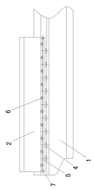
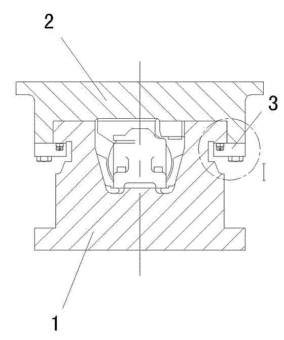
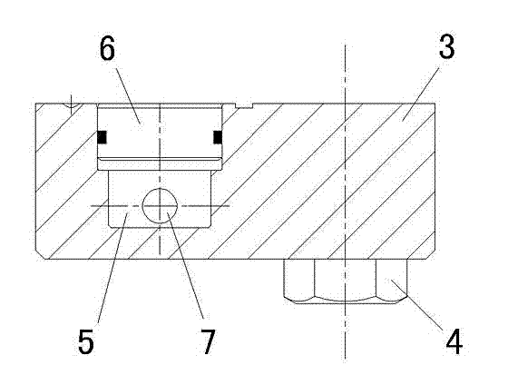
[0009] like figure 1 , 2 , 3: 1 is the guide rail of the machine tool, the guide rail 1 is equipped with a ram 2 that slides along the longitudinal direction of the guide rail, and a pressure plate 3 is fixed under the two sides of the ram 2 by bolts 4, and the pressure plate 3 is clamped on both sides of the guide rail. below. The pressure plate 3 is longitudinally provided with a hydraulic oil channel 5 that communicates with the hydraulic control mechanism. One end of the hydraulic oil channel 5 is an oil inlet 7, and the other end is blocked by a wire plug. A plurality of plungers 6 are arranged in a straight line inside the pressure plate 3 , the bottom surface of the plunger 6 is connected to the hydraulic oil channel 5 , and a sealing ring is arranged between the periphery of the plunger 6 and the pressure plate 3 .

[0010] The hydraulic oil channel 5 is connected to the hydraulic control device through pipelines and valves. When the ram 2 runs in place, each plunger...


PUM


Abstract

The invention discloses a ram enclasping mechanism which comprises a guide rail, wherein a ram is allocated on the guide rail and slides longitudinally along the guide rail, pressure plates are fixed below two sides of the ram, the pressure plates are clamped below the two side edges of the guide rail, hydraulic oil passages communicated with a hydraulic control mechanism are longitudinally arranged on the pressure plates, a plurality of plunger pistons are arrayed inside the pressure plates, the bottom surface of the plunger pistons are communicated with the hydraulic oil passages, and sealing rings are arranged between the peripheries of the plunger pistons and the pressure plates. According to the ram enclasping mechanism provided by the invention, the hydraulic oil passages are connected with the hydraulic control mechanism through pipelines and valves, when the ram runs to a proper position, all the plunger pistons can move upward under the effect of hydraulic oil and meanwhile press towards the positions below the two side edges of the guide rail, so as to enable the ram to enclasp the guide rail, the positioning on the ram is no longer achieved through the driving mechanism of the ram, the flexibility is good, the positioning is timely and reliable, and the entire structure is simple.

Description

technical field [0001] The invention relates to a gripping mechanism, in particular to a ram gripping mechanism, which is used for gripping and locking between a guide rail and a ram matched with it. Background technique [0002] The guide rail and the ram matched with the guide rail are commonly used parts of the machine tool, and the ram can slide longitudinally along the guide rail under the drive of the driving mechanism. In the existing ram mechanism, when the ram runs in place, its locking is realized by the stop of the driving mechanism. Due to the intermediate transmission components, the transmission components will have a certain gap, and the ram will not stop and position in time due to inertia, and the flexibility is poor. The machining of the workpiece has a certain influence. SUMMARY OF THE INVENTION [0003] The purpose of the present invention is to provide a ram holding mechanism with simple structure, flexible and reliable action, and can stop holding th...

Claims


Application Information

Patent Timeline
IPC IPC(8): B23Q1/26
CPCB23Q5/52
Inventor 关长明刘晏杨曙光
Owner DALIAN HUAGEN MACHINERY
Features
  • Generate Ideas
  • Intellectual Property
  • Life Sciences
  • Materials
  • Tech Scout
  • Unparalleled Data Quality
  • Higher Quality Content
  • 60% Fewer Hallucinations
Learn More