SMT printing machine steel mesh positioning device

A technology for positioning devices and printing machines, applied to printing machines, rotary printing machines, screen printing machines, etc., can solve the problems of reducing the working efficiency of SMT printing machines, the printing machine steel mesh cannot be positioned, and the assembly process is cumbersome, etc., to achieve maintenance Convenience, low cost, and short assembly time

Active Publication Date: 2016-01-27
东莞市九方电子设备有限公司
View PDF8 Cites 0 Cited by
  • Summary
  • Abstract
  • Description
  • Claims
  • Application Information

AI Technical Summary

Problems solved by technology

[0003] 1. When assembling, it is necessary to thread a drawstring and connect the drawstring to each pressing block, so the assembly process is very cumbersome, time-consuming, inefficient, and inconvenient to assemble;
[0004] 2. During use, the pull rope is prone to breakage, which causes the stencil of the printing machine to be unable to be positioned, and the pull rope needs to be re-threaded. The maintenance time generally takes two hours, so the maintenance is very time-consuming, and the maintenance cost is greatly increased. At the same time, it still leads to a great reduction in the working efficiency of the SMT printing machine.

Method used


Image

  • SMT printing machine steel mesh positioning device
  • SMT printing machine steel mesh positioning device
  • SMT printing machine steel mesh positioning device

Examples


Embodiment Construction

[0024] In order to understand the above-mentioned purpose, features and advantages of the present invention more clearly, the present invention will be further described in detail below in conjunction with the accompanying drawings and specific embodiments.

[0025] In the following description, more specific details are set forth in order to fully understand the present invention. However, the present invention can also be implemented in other ways different from those described here. Therefore, the protection scope of the present invention is not limited by the following disclosure. Limitations of specific embodiments.

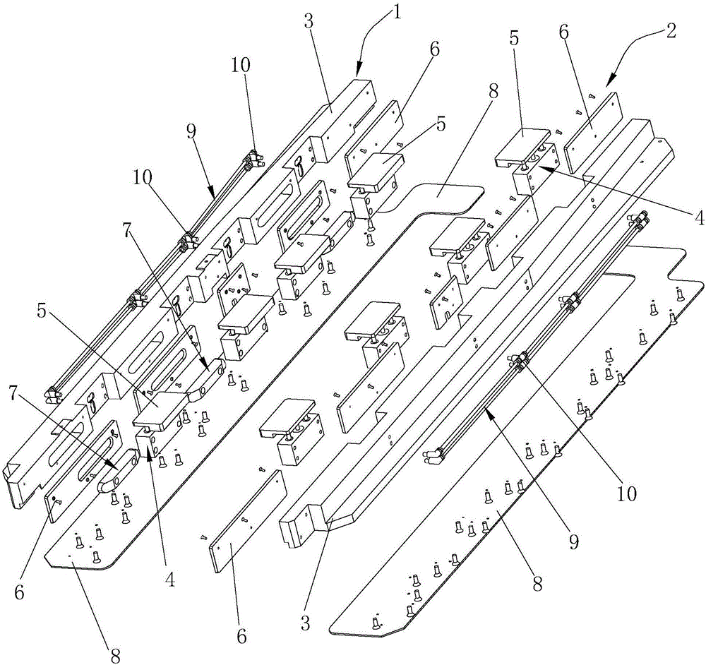
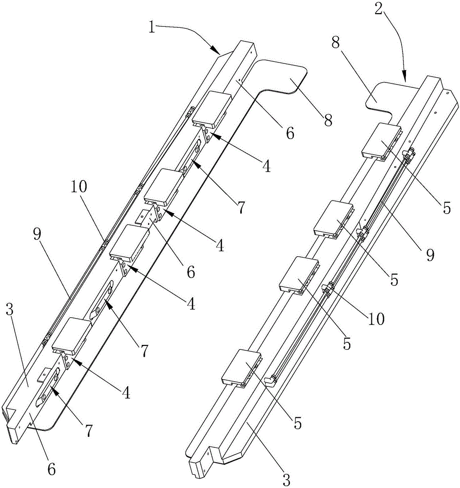
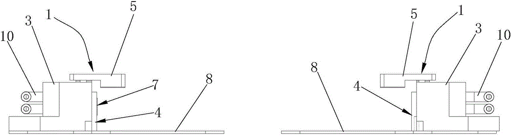
[0026] refer to Figure 1 to Figure 6 , provide a SMT printing machine stencil positioning device, including a first positioning mechanism 1 and a second positioning mechanism 2 for positioning the SMT printing machine stencil oppositely arranged, the first positioning mechanism 1 and the second positioning mechanism 2 respectively comprise a steel mesh pos...


PUM


Abstract

The invention discloses an SMT printer stencil positioning device comprising a first positioning mechanism and a second positioning mechanism facing to each other. Each of the first and second positioning mechanisms comprises a stencil positioning frame, at least one compressing positioning cylinder, and a pressure plate, wherein the compressing positioning cylinders are mounted on the stencil positioning frame in an embedded manner and the pressure plate is mounted on the compressing positioning cylinders. The compressing positioning cylinders can drive the pressure plates to move up and down, thus an SMT printer stencil can be accurately positioned, positioning is highly accurate and stable, and printing precision and production efficiency are high. In addition, the compressing positioning cylinders and the pressure plates coordinate to accurately and reliably position the stencil, so that the SMT printer stencil positioning device is simple to assemble, assembly time is short, assembly efficiency is high, the SMT printer stencil positioning device is long in service life, simple to maintain later, maintenance time is short, and maintenance cost is low.

Description

technical field [0001] The invention relates to the field of surface mount technology (SMT), and more specifically relates to a steel mesh positioning device for an SMT printing machine. Background technique [0002] The traditional SMT printer stencil positioning device for printing solder paste or red glue on a printed circuit board includes a first support frame and a second support frame, and the first support frame and the second support frame are respectively equipped with pull ropes Cylinder, several briquetting blocks and pull ropes, the pull ropes are connected to the front ends of each briquetting block, the upper end of each briquetting block is rotatably connected to the corresponding support frame through a rotating shaft, and the pull rope is tightened by the pull rope cylinder to make each briquetting block go down Movement compresses the steel mesh. The stencil positioning device of this type of structure has the following defects: [0003] 1. When assembli...

Claims


Application Information

Patent Timeline
Patent Type & Authority Patents(China)
IPC IPC(8): B41F15/36
Inventor 罗安松汤志
Owner 东莞市九方电子设备有限公司
Why Eureka
Try Eureka