Eddy current retarder with torsional vibration reduction function

A technology of eddy current retarder and torsional vibration reduction, which is applied in springs/shock absorbers, motors, electric vehicles, etc., and can solve the problem of large fluctuations in rear axle gear load, large vibration and noise, and affecting the service life of rear axles, etc. question

Active Publication Date: 2014-04-02
ZHENGZHOU YUTONG BUS CO LTD
View PDF4 Cites 9 Cited by
  • Summary
  • Abstract
  • Description
  • Claims
  • Application Information

AI Technical Summary

Problems solved by technology

On the one hand, when the retarder is braking, the braking force comes from before the main reducer of the rear axle, and the braking torque is opposite to the driving torque. At this time, the rotation speed of the driven gear of the main 1. The passive gear is in the meshing state of the back of the teeth. Due to the large reaction torque and the meshing accuracy of the main minus back teeth, the rear axle is prone to generate large vibration and noise at this time. At the same time, the instantaneous braking torque acts on the drive train. It will have a large impact on the gears of the gearbox, especially the gears of the rear axle, which will aggravate the vibration and noise of the rear axle and affect the service life of the rear axle; on the other hand, when the retarder is not braking, the vehicle will The rear axle gear drives the transmission shaft and the retarder rotor. Due to the large moment of inert

Method used


Image

  • Eddy current retarder with torsional vibration reduction function
  • Eddy current retarder with torsional vibration reduction function
  • Eddy current retarder with torsional vibration reduction function

Examples


Embodiment Construction

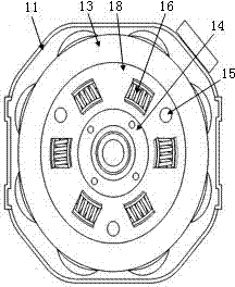
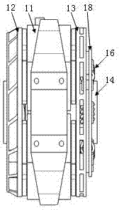
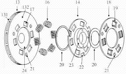
[0021] Examples of eddy current retarders with torsional vibration damping, such as Figure 1-3 As shown, the eddy current retarder with torsional vibration damping function includes a stator 11, an upstream rotor 12 and a downstream rotor 13, the upstream rotor 12 is used for connecting with the vehicle gearbox, and the downstream rotor 13 is used for connecting with the front end drive shaft of the rear axle of the vehicle connect. In addition, the downstream rotor 13 is provided with a vibration damping device for connecting with the drive shaft at the front end of the rear axle of the vehicle.

[0022] In this embodiment, the downstream rotor 13 is composed of an inner disk 131 and an outer disk 132 fixed together. There is a gap between the inner and outer disks, and the two are connected together by some connecting ribs at the edges. It is transmitted from the upstream rotor 12 to the outer disk 132 through the inner disk 131 . The shock absorbing and buffering device ...


PUM


Abstract

The invention relates to an automobile braking device, in particular to an eddy current retarder with a torsional vibration reduction function. The eddy current retarder with the torsional vibration reduction function comprises a stator, an upstream rotor and a downstream rotor, wherein the upstream rotor is used for being connected with an automobile gear box, the downstream rotor is used for being connected with a transmission shaft on the front end of a rear axle, and a vibration reduction buffering device used for being connected with the transmission shaft on the front end of the rear axle is arranged on the downstream rotor. During operation, a torsional countermoment which is instantaneously generated acts on the vibration reduction buffering device, so as to reduce torque impact which is instantaneously generated through the buffering and damping effects of the vibration reduction buffering device, thereby achieving the purpose of reducing impact and vibration; in addition, when the retarder is not braked, the vibration reduction buffering device is connected into a transmission system in series, so as to be favorable for reducing torque fluctuation which is generated by an engine and a shafting space angle and improving the NVH (Noise, Vibration and Harshness) performance of the transmission system. In conclusion, by using the eddy current retarder, vibration and noise caused by the retarder to an automobile can be reduced.

Description

technical field [0001] The invention relates to an automobile braking device, in particular to an eddy current retarder with torsional damping function. Background technique [0002] The eddy current retarder is a vehicle auxiliary braking device. It is generally composed of a stator, a stator bracket and a rotor coaxially arranged on both sides of the stator. It is often installed between the automobile drive axle and the gearbox. contact brake. When the retarder is working, the stator coil is energized to generate a magnetic field. At this time, the rotor rotating with the drive shaft will cut the magnetic field lines generated by the stator, thereby generating a vortex-shaped induced current inside the rotor disk, and the stator will flow to the rotor at the same time. Apply an electromagnetic force that hinders the rotation of the rotor, and then generate a braking torque to form a braking effect. [0003] The eddy current retarder can effectively improve the braking s...

Claims


Application Information

Patent Timeline
IPC IPC(8): B60L7/28F16F15/134F16F15/139
CPCB60L7/28B60L2220/10B60L2270/145F16F15/123F16F15/129H02K49/04Y02T10/64
Inventor 王占彬侯俊剑王亚奎张博强谢富科魏亚鹏
Owner ZHENGZHOU YUTONG BUS CO LTD
Why Eureka
Try Eureka