A device for automatic phosphating of pistons

A piston and automatic technology, applied in the direction of metal material coating process, etc., can solve the problems that the quality of piston phosphating cannot be guaranteed, affect the quality of piston phosphating, and the flow effect is not very good, so as to reduce the labor intensity of workers and structure Simple, easy to debug effect

Active Publication Date: 2016-02-24
BINZHOU BOHAI PISTON CO LTD +1
View PDF5 Cites 0 Cited by
  • Summary
  • Abstract
  • Description
  • Claims
  • Application Information

AI Technical Summary

Problems solved by technology

Some piston manufacturers adopt a cantilever structure. The piston is installed on the hook of the material frame, and the cylinder is used to lift and move the piston material frame. It is in a static state, causing the inner cavity of the piston to suffocate, and the phosphating effect is not good
There are also some piston manufacturers who add air-blown water devices on this basis to realize the agitation of the liquid. Due to the large volume of the liquid, the flow effect in the tank is not very good.
At the same time, where the hook is in contact with the piston, it cannot be phosphated at all, which seriously affects the quality of phosphating and causes the piston to rust
[0004] There are also piston phosphating equipment used by some piston manufacturers, which are improved on the basis of general-purpose component phosphating equipment. The trolley adopts a gantry structure and has no protection. When people come into close contact with the moving trolley, there are potential safety hazards, and there is no phosphating solution filter device. , long-term use will seriously affect the quality of piston phosphating
Although this equipment is equipped with a rotating material frame, it does not adopt the special rotating hanger used in the present invention, and its piston is prone to bumping in the material frame, and the piston inner cavity will hold air at the same time, and it will also occur on the top surface of the piston and the stop. Blind spots where phosphating cannot be achieved, so that the quality of piston phosphating cannot be guaranteed

Method used


Image

  • A device for automatic phosphating of pistons
  • A device for automatic phosphating of pistons
  • A device for automatic phosphating of pistons

Examples


Embodiment Construction

[0063] The present invention will be further described below in conjunction with the accompanying drawings.

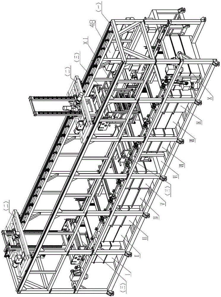
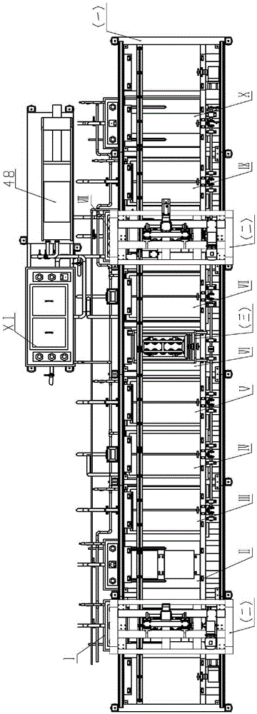
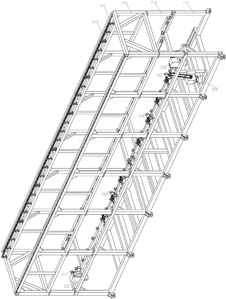
[0064] figure 1 , figure 2 It is an overall assembly diagram of the present invention, which includes main frame one, manipulator two, rotating hanger three, phosphating process tank (ultrasonic cleaning tank I, ultrasonic cleaning tank II, rinsing tank III, pickling tank IV, rinsing tank V, table Regulating tank VII, phosphating tank VIII, rinsing tank IX, hot water washing tank X, phosphating tank XI) and filter press 48. Two slide rails 4 are installed on the top surface of the main frame one. The roller 29 of the manipulator two is fixed on the slide rails 4. The manipulator two drives the rotating hanger three according to the phosphating process. After staying in each groove for a certain period of time, it automatically moves to the bottom. a slot. When the rotating hanger 3 falls into the groove, the gear III53 meshes with the gear VII 6 to drive the rotati...


PUM


Abstract

The invention discloses a device for automatic piston phosphatization. The device comprises a main frame, wherein two manipulators are arranged at the top of the main frame and can move back and forth along the main frame; a plurality of phosphatization process tank groups are arranged at the bottom of the main frame according to the technical process; the manipulators are matched with rotary hanging racks which can move among the phosphatization process tank groups; a filter press and a phosphatizing tank XI are arranged on the outer side of the main frame; the phosphatizing tank XI, the filter press and a phosphatizing tank VIII in the main frame are connected to form a circulating filtration mechanism for filtering a phosphatizing solution. The main body is frame-shaped; the device is simple in structure, convenient to mount, debug and protect and the working environment is safe and sanitary. The device adopts an automatic production manner to greatly improve the production efficiency and reduce the labor intensity of workers. The filter mechanism is used to filter the phosphatizing solution in order to implement recycling on the phosphatizing solution, and further reduce the use cost.

Description

technical field [0001] The invention relates to a device for automatic phosphating of pistons. Background technique [0002] With the continuous development of the engine towards low fuel consumption, low noise and low emission, people have higher and higher requirements for the piston, which is the heart part of the engine. How to ensure the quality of pistons and improve production efficiency is a topic that domestic piston manufacturers are very concerned about. [0003] At present, for the implementation of the piston automatic phosphating process, there is no mature equipment dedicated to the automatic phosphating of pistons in China. Most of the piston manufacturers still adopt the mode of manual phosphating, which is not only labor-intensive for workers, but also seriously endangers the health of operators due to the toxicity and corrosion of phosphating solution. Some piston manufacturers adopt a cantilever structure. The piston is installed on the hook of the mate...

Claims


Application Information

Patent Timeline
Patent Type & Authority Patents(China)
IPC IPC(8): C23C22/73
Inventor 赵国华张峰于志勇郭小鹏宋立科
Owner BINZHOU BOHAI PISTON CO LTD
Why Eureka
Try Eureka