Movable reinforcement cage binding jig

A steel cage and mobile technology, applied in water conservancy projects, reinforced molding, artificial islands, etc., can solve the problems of long construction period, inconvenient construction, affecting binding efficiency, and the convenience of precision installation and disassembly, so as to achieve convenient movement and improve The effect of ergonomics and precision

Inactive Publication Date: 2014-04-02
CCCC SECOND HARBOR ENG +3
View PDF7 Cites 15 Cited by
  • Summary
  • Abstract
  • Description
  • Claims
  • Application Information

AI Technical Summary

Problems solved by technology

[0003] For the forming of large-volume steel cages, at present, the method of pouring in stages, formwork as the steel cage frame, and other supports or scaffolding as the frame is basically adopted. The support method is fixed and cannot be adjusted. The construction period is long and the c

Method used


Image

  • Movable reinforcement cage binding jig
  • Movable reinforcement cage binding jig

Examples


Embodiment Construction

[0022] The specific implementation manners of the present invention will be further described in detail below in conjunction with the accompanying drawings and embodiments. The following examples are used to illustrate the present invention, but are not intended to limit the scope of the present invention.

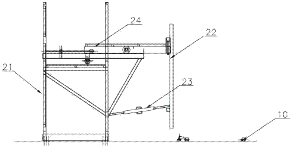
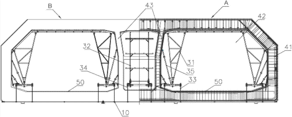
[0023] Such as figure 1 and figure 2 shown, (where, figure 2 The first support frame is not shown in, and figure 2 The center is divided into two areas, A and B, the area of ​​A is the structure bound with the steel cage, and the structure not bound with the steel cage in the area B), a kind of movable steel cage binding tire frame of the present invention, it comprises sliding Rail 10, outer tire frame and inner tire frame, described slide rail is a plurality of parallel setting, wherein, outer tire frame is fixedly arranged on the outside of reinforcement cage, and inner tire is erected in the inside of reinforcement cage and is positioned on slide rail 10. At the...


PUM


Abstract

The invention relates to the field of immersed tube tunnels, in particular to a movable reinforcement cage binding jig, which comprises a plurality of sliding tracks, an outer jig and an inner jig, wherein the sliding tracks are arranged in parallel, the outer jig is fixed out of a reinforcement cage, the inner jig is arranged in the reinforcement cage and is positioned on the sliding tracks, and the inner jig can move along the sliding tracks. The inner jig and the reinforcement cage of the movable reinforcement cage binding jig are arranged on the sliding tracks and can be removed and conveniently moved, the movable reinforcement cage binding jig is suitable for factory large-sized prefabricated parts, and a movable jig structure which can be quickly installed and removed is adopted, so that the work efficiency and the precision of binding the reinforcement cage are improved.

Description

technical field [0001] The invention relates to the field of immersed tube tunnels, in particular to a movable steel cage binding tire frame. Background technique [0002] The immersed tube used in the subsea tunnel prefabrication project is a large-scale factory prefabricated component: its height is about 1200cm, its width is about 3800cm, and its length is about 2300cm. The immersed tube is made of concrete poured into a steel cage. [0003] For the forming of large-volume steel cages, at present, the method of pouring in stages, formwork as the steel cage frame, and other supports or scaffolding as the frame is basically adopted. The support method is fixed and cannot be adjusted. The construction period is long and the construction is inconvenient. This method is not applicable. Factory large-scale prefabricated components, especially for the formation of ultra-large, ultra-wide, and ultra-high steel cages, have seriously affected the efficiency, accuracy, and convenien...

Claims


Application Information

Patent Timeline
IPC IPC(8): E02D29/07E02D29/073B28B21/56
Inventor 张洪周光强杨永宏刘经国刘全戴书学李诗明
Owner CCCC SECOND HARBOR ENG
Why Eureka
Try Eureka