Comprehensive mechanical property test device of fuel assembly and test method thereof
A fuel assembly, comprehensive mechanics technology, applied in the direction of measurement device, analysis material, strength characteristics, etc., can solve the problem of no fuel assembly comprehensive mechanical performance test device patent, no fuel assembly comprehensive mechanical performance test device description and other problems, to avoid The effect of test data inaccuracy and ensuring measurement accuracy
- Summary
- Abstract
- Description
- Claims
- Application Information
AI Technical Summary
Problems solved by technology
Method used
Image
Examples
Embodiment 1
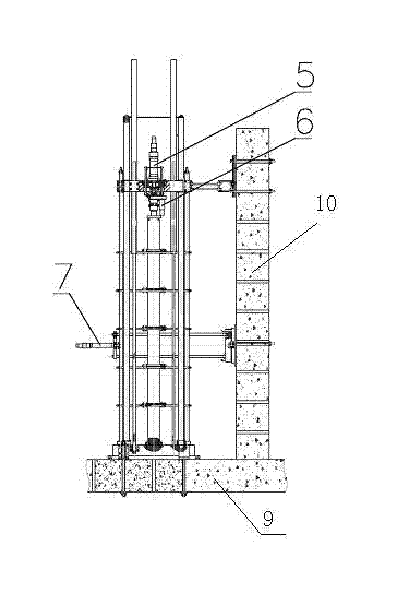
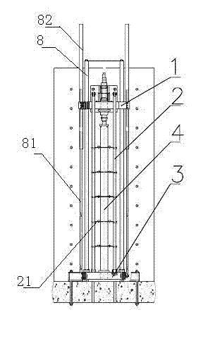
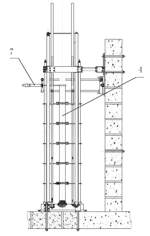
[0046] Such as Figure 1 to Figure 5 shown.
[0047] The fuel assembly comprehensive mechanical performance test device includes a horizontal support platform 9 and a vertical support platform 10 placed on the horizontal support platform 9; a base 3 is installed on the horizontal support platform 9, and at least 3 axes perpendicular to the horizontal are installed on the base 3 The loading column 8 on the upper surface of the support platform 9, the base 3 is equipped with at least two measuring columns 2 whose axes are perpendicular to the upper surface of the horizontal support platform 9; The support platform is connected, and the end of the loading column 8 away from the base 3 runs through the loading top plate 1, and the loading top plate 1 is provided with a through hole for placing the fuel assembly under test.
[0048] The design principle of the present invention is: the present invention is specially configured as the above-mentioned device according to the charact...
Embodiment 2
[0062] Experimental methods, including component tension and compression tests, the specific experimental steps are:
[0063] A1. Lift the tested fuel assembly 4 vertically through the through hole for the tested fuel assembly. After the lower end of the tested fuel assembly 4 is fixed on the base, install the vertical loading mechanism 5 in place from above the loading top plate 1. The upper end of the fuel assembly 4 is connected with the output end of the vertical loading mechanism 5, and the verticality of the measured fuel assembly 4 is adjusted; preferably, the lower end of the measured fuel assembly 4 is fixed with the pin on the clamp on the base; it is connected with the measuring column An eddy current displacement sensor or a differential transformer type displacement sensor or a laser displacement sensor is arranged on the limit device; the surface of the measured fuel assembly 4 is attached with a strain gauge for measuring assembly strain, etc.
[0064] B1. Apply...
Embodiment 3
[0067] Such as figure 1 with figure 2 As shown, the described experimental method also includes the component torsion test, and its specific experimental steps are:
[0068] A2. Hang the tested fuel assembly 4 vertically through the through-hole of the tested fuel assembly. After the lower end of the tested fuel assembly 4 is fixed to the base, install the torsional loading mechanism 6 on the loading top plate. The upper end is connected to the output end of the torsion loading mechanism 6; an eddy current displacement sensor or a differential transformer type displacement sensor or a laser displacement sensor is arranged on the limit device connected to the measuring column; the surface of the measured fuel assembly 4 is attached with a measuring assembly Strain gauges, etc.
[0069] B2. Apply torsional force to the tested fuel assembly 4 through the torsion loading mechanism 6, measure the rotation angle and lateral deformation index of the tested fuel assembly 4 at the s...
PUM
 Abstract
Description
Claims
Application Information
 - R&D
- Intellectual Property
- Life Sciences
- Materials
- Tech Scout
- Unparalleled Data Quality
- Higher Quality Content
- 60% Fewer Hallucinations
Browse by: Latest US Patents, China's latest patents, Technical Efficacy Thesaurus, Application Domain, Technology Topic, Popular Technical Reports.
© 2025 PatSnap. All rights reserved.Legal|Privacy policy|Modern Slavery Act Transparency Statement|Sitemap|About US| Contact US: help@patsnap.com


