Manipulator

A technology of manipulators and connecting parts, applied in the field of manipulators, can solve cumbersome problems, and achieve the effect of improving convenience and simplifying the clamping process.

Active Publication Date: 2014-04-02
NINGBO YINGMING ELECTRIC TECH
View PDF5 Cites 4 Cited by
  • Summary
  • Abstract
  • Description
  • Claims
  • Application Information

AI Technical Summary

Problems solved by technology

[0005] However, the manipulator in the prior art is relatively

Method used


Image

  • Manipulator
  • Manipulator
  • Manipulator

Examples


Embodiment Construction

[0033] As mentioned in the background technology section, the process of clamping the fiber core connector by the manipulator in the prior art is relatively cumbersome.

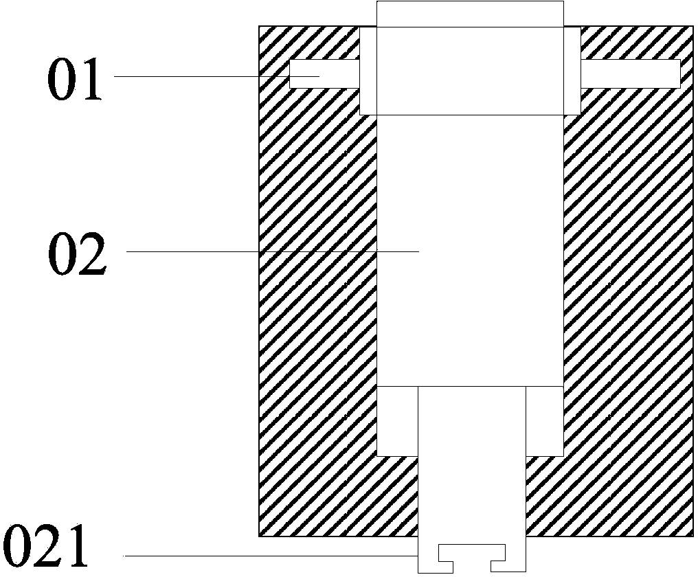
[0034] Such as figure 1 As shown, the manipulator in the prior art includes: a transmission gear 01, which is threadedly connected with the transmission gear 01, and a plugger 02 concentric with the transmission gear 01, wherein the bottom of the plugger 02 is provided with The clamping part 021 is used for clamping the fiber core connector.

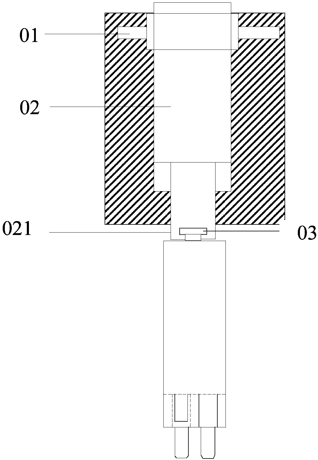
[0035] The inventors have found through research that, since the aperture of the opening of the clamping part 021 of the manipulator in the prior art is smaller than the aperture of the part to be clamped in the fiber core connector (such as figure 2 shown), so that when using the clamping part 021 to clamp the fiber core connector, the two arms of the clamping part 021 need to move a certain distance to both sides in the horizontal direction until The caliber of the...


PUM


Abstract

The embodiment of the invention discloses a manipulator, comprising a transmission device, a first structure part, a second structure part and an elastic structure, wherein the cross section of a second connection part in the first structure part is gradually increased along the direction from a first connection part to the second connection part; the second structure part is hinged to the second connection part, so under the action of the elastic structure, a first state in which the distance between a first clamping angle and a second clamping angle is smaller than the distance between a first clamping arm and a second clamping arm is recovered from a second state in which the distance between the first clamping angle and the second clamping angle is larger than the distance between the first clamping arm and the second clamping arm, and the first state can become the second state under the action of an external force, so when the manipulator is used for clamping a fiber core connector, only the second structure part needs to be moved in the vertical direction, the process for clamping the fiber core connector by using the manipulator is simplified and the portability for clamping the fiber core connector by the manipulator is improved.

Description

technical field [0001] The invention relates to the technical field of optical networks, in particular to a manipulator. Background technique [0002] With the rapid development of power grid construction and the continuous improvement of the automation of power system equipment, the optical fiber power communication network has also achieved unprecedented development. At present, as the basic bearer network of optical fiber communication transmission - optical fiber network, its switching equipment is the key equipment to complete the exchange between optical fibers. [0003] The switching equipment in the prior art includes: a docking board, the docking board has a plurality of docking holes, wherein at least one pair of docking holes are respectively fixed with the fiber cores at both ends of the pigtail, and each pair of docking holes is connected by a pigtail A fiber core connector, one end of an external access fiber core is fixed on the fiber core connector, and the ...

Claims


Application Information

Patent Timeline
IPC IPC(8): G02B6/38B25J11/00B25J15/08
Inventor 张莉王焱孙淳
Owner NINGBO YINGMING ELECTRIC TECH
Why Eureka
Try Eureka