
Wideband dual-polarization array antenna and base station

An array antenna and dual-polarization technology, which is applied to antenna unit combinations, antennas, and antenna arrays with different polarization directions, can solve the problems of reduced bandwidth and efficiency, and achieve the effect of reduced standing wave ratio and good broadband performance

Active Publication Date: 2014-04-02
HUAWEI TECH CO LTD
View PDF4 Cites 29 Cited by
  • Summary
  • Abstract
  • Description
  • Claims
  • Application Information

AI Technical Summary

Problems solved by technology

Reduction in antenna size means reduction in other properties of the antenna, such as bandwidth and efficiency

Method used


Image

  • Wideband dual-polarization array antenna and base station
  • Wideband dual-polarization array antenna and base station
  • Wideband dual-polarization array antenna and base station

Examples


Embodiment 1

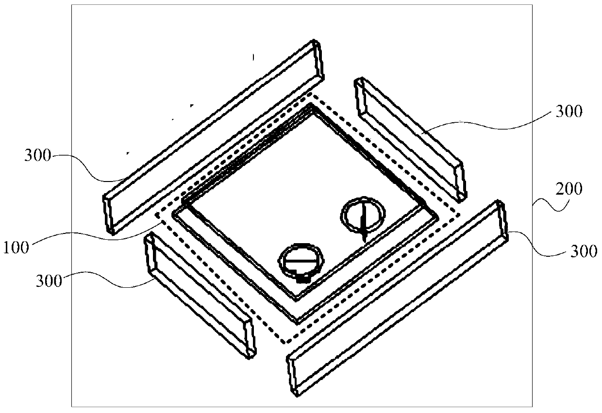
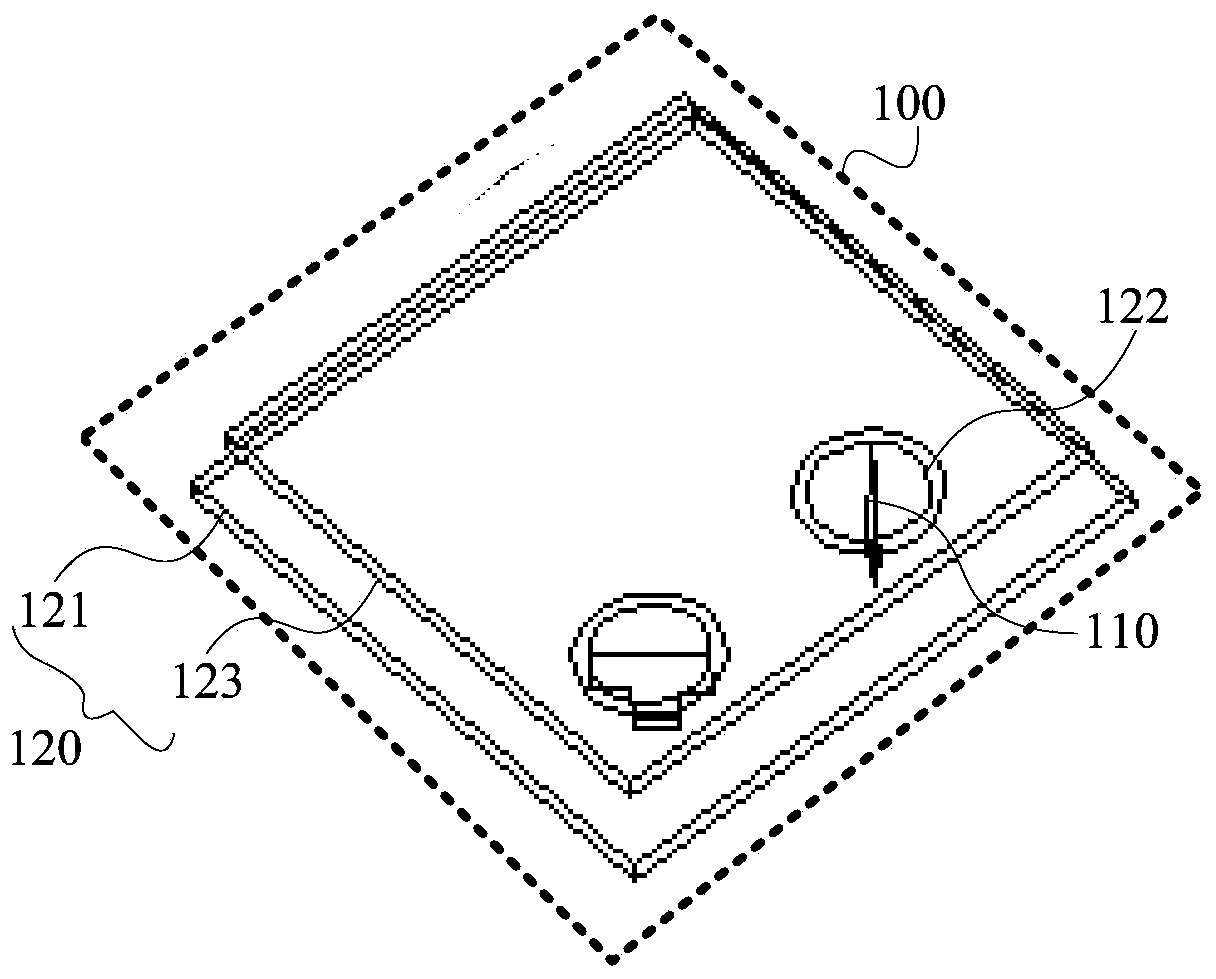
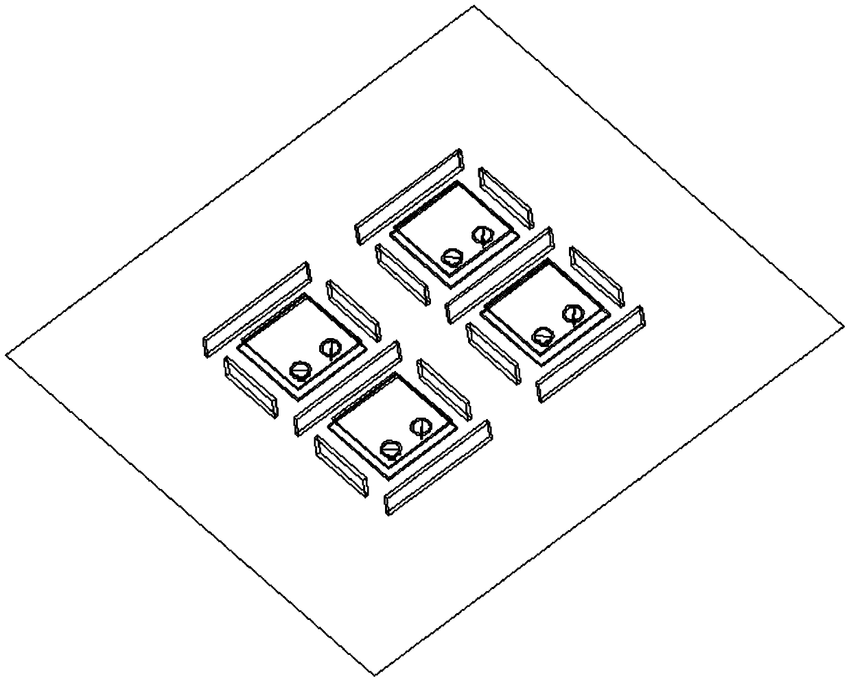
[0027] figure 1 It is a schematic diagram of the overall structure of Embodiment 1 of the broadband dual-polarized array antenna of the present invention, figure 2 It is a schematic structural diagram of the antenna unit in Embodiment 1 of the broadband dual-polarization array antenna of the present invention. An embodiment of the present invention provides a broadband dual-polarization array antenna, and the broadband dual-polarization array antenna can be integrated in a base station. Wherein, there may be one or more antenna units in the array antenna, and the plurality of antenna units may be regularly arranged in a line array or a planar array, or randomly arranged. In this embodiment, an area array structure in which 2*2 antenna elements are regularly arranged is taken as an example for illustration, as image 3 shown.

[0028] Such as figure 1 and figure 2 As shown, the broadband dual-polarized array antenna includes an antenna unit 100, a metal reflector 200 and...

Embodiment 2

[0041] In the embodiment of the present invention, the broadband dual-polarization array antenna adopts such as image 3 In the structure shown, the dielectric plate with a relative permittivity of 4 is selected for the double-layer radiation patch, the copper plate is used for the feeder plate, and the aluminum plate is used for the metal isolation plates in the horizontal direction and the vertical direction.

[0042] The performance of the broadband dual-polarized array antenna provided by the present invention is further illustrated through the following simulations:

[0043] 1. Simulation content

[0044] The broadband dual-polarized array antenna is simulated by using simulation software, and the simulation results are obtained by observing the standing wave ratio of the feed port and the isolation between the feed ports.

[0045] 2. Simulation results

[0046] Figure 6 It is the reflection coefficient curve diagram of itself when the first feeding port is the input ...


PUM


Abstract

The embodiment of the invention discloses a wideband dual-polarization array antenna and a base station, wherein the wideband dual-polarization array antenna includes an antenna unit, a metal reflection board, and a metal separation board, the antenna unit being separated by the metal separation board. The antenna unit contains a feed piece and a double-layer radiation patch. A first end of the feed piece is configured at the bottom radiation patch of the double-layer radiation patch so as to form a feeding point, and a second end of the feed piece is connected to a feed structure so as to form a feeding port. The bottom patch of the double-layer radiation patch is provided a slot at the upper surface thereof. A hole is opened within the slot to fixedly connect the fist end of the feed piece in order to form capative reactance. The embodiment of the invention form capative reactance by providing a slot on the upper surface of the bottom patch of the double-layer radiation patch of the array antenna, which enables an easy resonance in each radiation patch of the double-layer radiation patch of the array antenna. The array antenna can realize wideband with efficiency.

Description

technical field [0001] Embodiments of the present invention relate to wireless communication technologies, and in particular to a broadband dual-polarization array antenna and a base station. Background technique [0002] With the rapid development of wireless communication technology, the bandwidth and performance requirements of antennas are getting higher and higher. Whether it is a military communication or a civilian communication system, there is a demand for high-performance base station antennas. [0003] The size and bandwidth of the antenna in the prior art are the main obstacles restricting the miniaturization of the communication system. A reduction in the size of the antenna means a reduction in other performances of the antenna, such as bandwidth and efficiency. Therefore, the miniaturization design of the communication system needs to find a compromise in the performance parameters of the antenna, such as directivity coefficient, gain, radiation efficiency, ...

Claims


Application Information

Patent Timeline
IPC IPC(8): H01Q21/24H01Q23/00H01Q1/36H01Q1/38
CPCH01Q5/40H01Q9/0414H01Q9/0435H01Q21/065
Inventor 赵建平张关喜谢中山
Owner HUAWEI TECH CO LTD
Learn More