Eureka AIR delivers breakthrough ideas for toughest innovation challenges, trusted by R&D personnel around the world.

Plugging device

An occluder and waveform technology, which is applied in the field of medical devices, can solve the problems of residual shunt, affect the occlusion effect, and keep it unchanged, so as to reduce the residual shunt, improve the occlusion effect, and reduce the gap

Active Publication Date: 2014-04-09
LIFETECH SCIENTIFIC (SHENZHEN) CO LTD
View PDF15 Cites 17 Cited by
  • Summary
  • Abstract
  • Description
  • Claims
  • Application Information

AI Technical Summary

Problems solved by technology

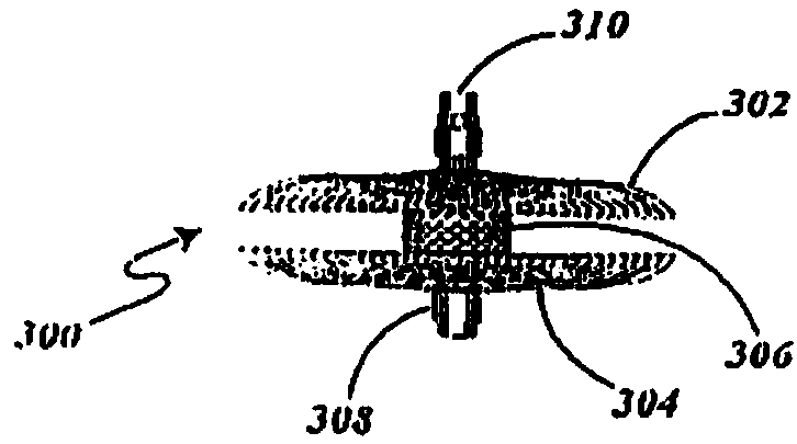
Therefore, after the occluder is implanted into the human body, the waist 51 cannot conform to the cross-sectional shape of the irregular defect, which will cause a certain residual shunt and affect the occlusion effect.
[0009] It can be seen from the above that although the occluders of the above various structures can easily enter the delivery sheath which is much smaller than its diameter, and realize the occlusion of the cardiac septal defect or blood vessel after release, but in the occlusion Defects with irregular cross-sections whose waists cannot ensure that their circumference remains basically unchanged to conform to defects with irregular cross-sections
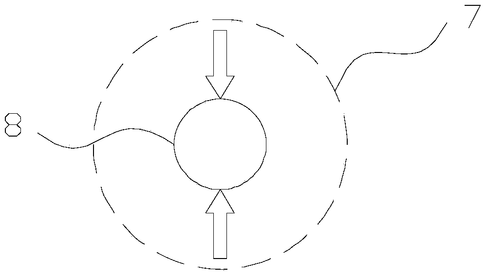
When the waist of the occluder with the above structure is subjected to a force in the direction of the maximum inner diameter, the size of the waist at the stressed part will shrink toward the inner diameter, but the size of the non-stressed or less stressed part will either shrink at the same time or remain In other words, the circumference of the waist is relatively reduced after being stressed, so that the waist of this type of occluder cannot fit the defect site completely, and there is a gap between the occluder and the defect site after implantation, thus forming a residual shunt and affecting the operation. Blocking effect

Method used

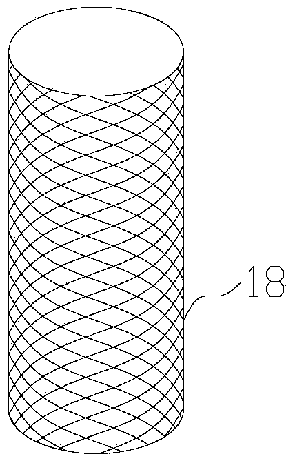

Image

  • Plugging device
  • Plugging device
  • Plugging device

Examples


Embodiment Construction

[0052] In order to make the object, technical solution and advantages of the present invention clearer, the present invention will be further described in detail below in conjunction with the accompanying drawings and embodiments. It should be understood that the specific embodiments described here are only used to explain the present invention, not to limit the present invention.

[0053] It should be noted that when an element is referred to as being “fixed on” or “disposed on” another element, it may be directly on the other element or there may be an intervening element at the same time. When an element is referred to as being "connected to" another element, it can be directly connected to the other element or intervening elements may also be present. In the field of interventional medicine, the end relatively close to the operator is defined as the proximal end, and the end relatively far away from the operator is defined as the distal end. In addition, the orientation t...


PUM


Abstract

The invention discloses a plugging device. The plugging device comprises at least one disc-shaped structure and a waist part connected with the disc-shaped structures, wherein the waist part comprises at least one wavelike ring, and the central axis of each wavelike ring is parallel to that of each disc-shaped structure. Because the waist part is provided with the wavelike rings, when the waist part is stressed with radial acting force, the wavelike structures of the wavelike rings act on the waist part in the radial direction so that the radial acting force can be transmitted in the peripheral direction of wavelike bodies, namely, the wavelike rings, thus, the perimeter of the waist part can be kept unchanged fundamentally under the radial acting force, axial tension is reduced as much as possible, even a coloboma part with an irregular section shape can be well attached to the wall of the plugging device, a gap between the waist part and the coloboma part can be reduced as much as possible, accordingly, residual shunts can be reduced, and the plugging effect can be improved.

Description

technical field [0001] The invention belongs to the technical field of medical instruments, in particular to an occluder. Background technique [0002] With the continuous development of interventional materials and instruments and interventional cardiology, minimally invasive treatment of congenital heart diseases such as atrial septal defect, ventricular septal defect, patent ductus arteriosus and patent foramen ovale by using catheter occluder has become an important method . Endovascular occlusion by interventional methods is also a widely accepted treatment. [0003] The occluder disclosed in the Chinese patent document whose application number is CN97194488.1 is as figure 1 As shown, the occluder 300 includes a plug head 310, a sealing head 308, a left disc 302, a right disc 304, and a waist 306; the left disc 302, the right disc 304, and the waist 306 are braided by multiple metal wires. During the preparation process, each metal wire forms two groups of metal wire...

Claims


Application Information

Patent Timeline
Patent Type & Authority Applications(China)
IPC IPC(8): A61B17/00A61F2/02
CPCA61B17/12109A61B17/12131A61B17/12145A61B2017/00606
Inventor 刘香东张德元陈杰付明娟
Owner LIFETECH SCIENTIFIC (SHENZHEN) CO LTD
Why Eureka
Eureka Blog
Learn More