sanitary cup

A sanitary cup and cup body technology, applied in the field of sanitary cups, can solve the problems of cumbersome use of sanitary cups, low user experience satisfaction, and large restrictions on use scenarios, so as to facilitate the promotion of use, increase the willingness to use, and improve satisfaction Effect

Active Publication Date: 2017-06-06
维爱科技(深圳)有限公司
View PDF7 Cites 2 Cited by
  • Summary
  • Abstract
  • Description
  • Claims
  • Application Information

AI Technical Summary

Problems solved by technology

[0006] The main technical problem to be solved by the present invention is to provide a sanitary cup, which solves the problems of cumbersome use process of existing sanitary cups, time-consuming, large restrictions on usage scenarios, and low user experience satisfaction

Method used


Image

  • sanitary cup
  • sanitary cup
  • sanitary cup

Examples


Embodiment 1

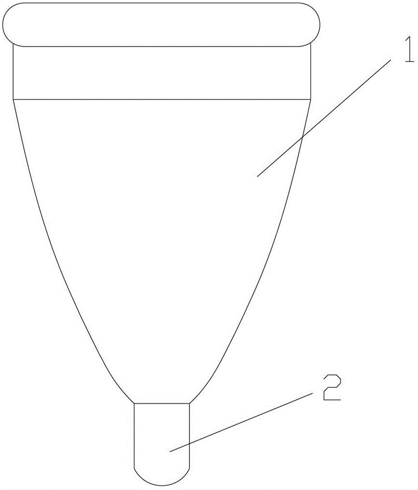
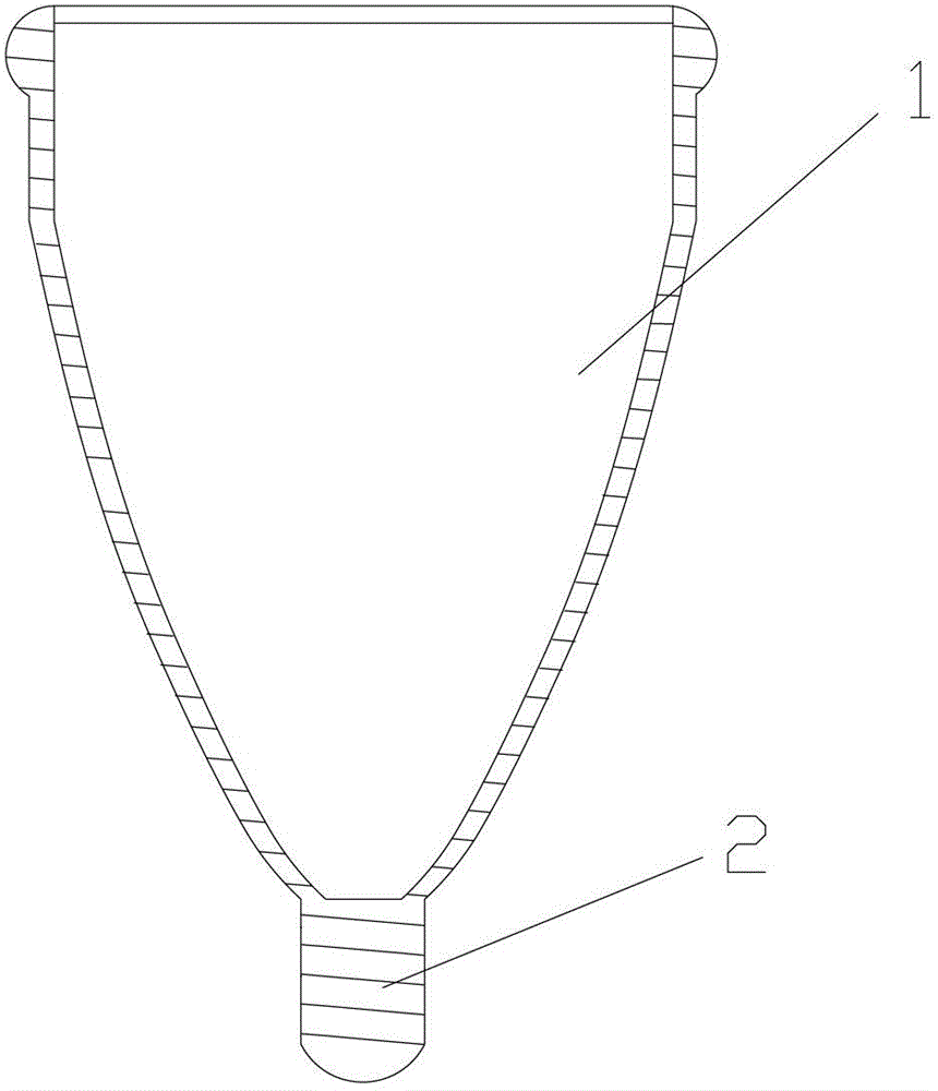
[0041]This embodiment provides a sanitary cup with good side leakage resistance, more comfortable, recyclable, low cost, more environmentally friendly, simpler and more convenient to use, the sanitary cup includes a cup body for collecting liquid, and The discharge pipe communicated with the bottom of the cup is provided with a discharge hole on the side wall of the discharge pipe; it also includes a switch device acting on the discharge pipe to control the liquid to flow through the discharge pipe to be discharged from the discharge hole. It should be noted that the bottom of the cup in this embodiment is not limited to the part of the cup farthest from the mouth of the cup, but generally refers to the lower part of the side wall of the cup. During use, it generally includes the liquid collection state (that is, the state that the sanitary cup is placed in the body to collect liquids such as menstrual blood) and the liquid discharge state (that is, the state that the liquid co...

Embodiment 2

[0047] In this embodiment, on the basis of the first embodiment above, the present invention will be further described by taking the switch device arranged in the discharge pipe as an example. When the switch device is arranged in the discharge pipe, it is more convenient to place the sanitary cup as a whole in the human body. The switch device arranged in the discharge pipe can control whether the liquid can be discharged from the discharge hole on the discharge pipe by controlling the closure and circulation of the discharge pipe hole; it can also directly control the opening and closing of the discharge hole arranged on the discharge pipe, so as to Control whether the liquid can flow out from the discharge hole; the following only takes several switch devices and the setting of the discharge hole as examples to illustrate.

[0048] One setting method is that the discharge hole is arranged on the side wall of the discharge pipe, that is, a side discharge type is used. A clo...

Embodiment 3

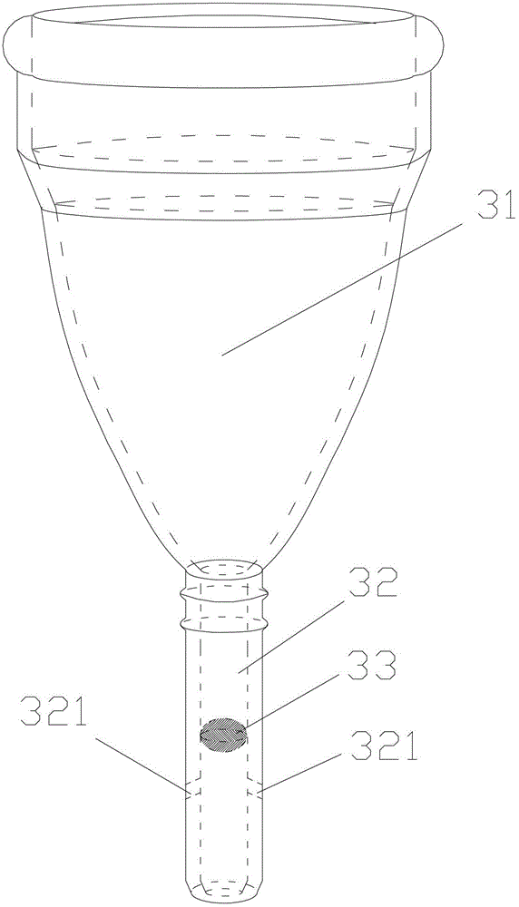
[0059] This embodiment also provides another arrangement of the switch device and the discharge hole, wherein the discharge hole can be arranged on the side wall of the discharge pipe, or at the bottom of the discharge pipe, or at the same time on the side wall or the discharge pipe. The bottom is provided with a discharge hole, and the switch device includes a switch valve arranged in the discharge pipe and above the discharge hole. When the switch valve is in the closed state, the pipe hole of the discharge pipe is sealed to prevent the liquid in the cup from flowing through the discharge pipe from the discharge hole. Exclusion; when the switch valve is in the open state, the pipe hole of the discharge pipe is not completely sealed, so that the discharge pipe is in a flow state, and then the flow between the discharge pipe and the discharge hole provided on it is made. The switching valve in this embodiment can be specifically an elastic valve device, specifically as Figure...


PUM


Abstract

The invention discloses a sanitary cup which comprises a cup, a drain pipe, drain holes and a switch gear. The drain pipe is communicated with the bottom of the cup, the drain holes are formed in the drain pipe, and the switch gear acts on the drain pipe, so that liquid can flow through the drain pipe to be drained from the drain holes under the control of the switch gear. During usage, the switch gear is turned off, then both the switch gear and the cup are placed into a human body, and the liquid flows into the cup and is stored in the cup; a user pulls the switch gear along the drain pipe or a pull handle out of the body of the user after a period of time, the pull handle is arranged on the cup, but the cup still remains in the body of the user, then the switch gear is turned on, and the liquid stored in the cup can flow through the drain pipe from the cup and is drained from the drain holes; the switch gear is turned off, and is pushed into the body of the user again, so that the cup can be located at a corresponding position in the human body. The sanitary cup has the advantages that the sanitary cup does not need to be frequently replaced or cleaned, is free of constraints on service places, can be used easily and conveniently as compared with an existing sanitary cup, and is high in user experience satisfaction.

Description

technical field [0001] The invention relates to a sanitary article, in particular to a sanitary cup. Background technique [0002] During the menstrual period, the most commonly used sanitary napkins by women are the sanitary napkins with high polymer water absorption. The use of sanitary napkins has the following problems: easy side leakage, which brings unacceptable embarrassment to users; poor air permeability, uncomfortable, when using It is very easy to get dirty during the process, and it is easy to induce various gynecological diseases. At the same time, all kinds of existing sanitary napkins can only be used once, consume a lot of resources, use high cost, and are not conducive to low-carbon environmental protection. In order to solve the above-mentioned various problems, there are recyclable sanitary cups on the market, see figure 1 and figure 2 As shown: the existing sanitary cup includes a cup body 1 and a handle 2 connected to the bottom, the bottom of the cup...

Claims


Application Information

Patent Timeline
Patent Type & Authority Patents(China)
IPC IPC(8): A61F5/455
CPCA61F5/4553A61F5/4405A61F5/4407
Inventor 唐志
Owner 维爱科技(深圳)有限公司
Why Eureka
Try Eureka