Integrated automatic microscopic welding equipment

A welding equipment and automatic spot welding technology, applied in welding equipment, resistance welding equipment, welding power sources, etc., can solve the problems of independent adjustment, the overall weight of the machine head, the accuracy of electrode force cannot meet the requirements of spot welding, etc., to achieve accurate electrode force The effect of improving output and spot welding accuracy

Inactive Publication Date: 2014-04-09
GUANGZHOU MICRO WELDING EQUIP
View PDF2 Cites 3 Cited by
  • Summary
  • Abstract
  • Description
  • Claims
  • Application Information

AI Technical Summary

Problems solved by technology

[0002] The CN1382557 patent announced by the Chinese Patent Office on December 4, 2002 discloses a double welding head spot welding machine, which mainly improves the welding head clamp, and the purpose is to optimize the welding effect, and the double welding head spot welding machine is theoretically Obviously, it can improve the efficiency of spot welding. However, the double welding head spot welding machine disclosed in the CN1382557 patent cannot independently adjust the electrode force of each parallel electrode and the electrical parameters of the welding energy output. Therefore, How to make the spot welding machine with double welding heads not only improve the efficiency of spot welding, but also obtain more accurate spot welding effect is one of the problems to be solved urgently in the industry
[0003] Specifically, the traditional resistance welding spot welding equipment has the fol

Method used


Image

  • Integrated automatic microscopic welding equipment
  • Integrated automatic microscopic welding equipment
  • Integrated automatic microscopic welding equipment

Examples


Embodiment Construction

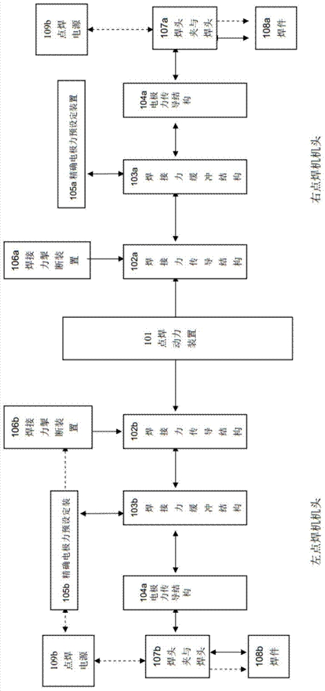
[0040] From the overall structure, the present invention can be divided into four parts, namely, two spot welding machine heads, two horizontal transverse clamp welding head clamps, spot welding power source and automatic spot welding power device. The spot welding power supply can be two spot welding power supplies connected to two horizontal clamp welding head clamps, or it can be connected to two horizontal clamp welding head clamps through the output end of one spot welding power supply, that is, two horizontal clamp welding head clamps. The welding head clamp can be powered by different spot welding power sources, or can be powered by the same spot welding power source. Since the spot welding power supply and the automatic spot welding power device are mastered by those skilled in the art, the present invention will not be described in detail, but will focus on the two parts of two spot welding machine heads and two horizontal clamp welding head clamps installed as a whole....


PUM


Abstract

The invention relates to automation of welding, in particular to integrated automatic microscopic welding equipment. Automatic welding of two weldments can be realized at the same time through two integrally-mounted spot welding machine headpieces, two horizontally-clamping welding head clamps, two spot welding power sources and an automatic spot welding power device, wherein the welding head clamps are arranged at the same horizontal position side by side; welding parameters of two parallel electrode welding heads are independently adjusted to guarantee welding reliability and uniformity. Through improvements of frames of the spot welding machine headpieces, gaps between the horizontally-clamping welding head clamps which are arranged at the same horizontal position side by side can be adjusted. The brand-new automatic welding equipment is provided for production of electronic components.

Description

Technical field [0001] The invention relates to welding automation, in particular to an integrated automatic micro welding equipment for resistance welding micro welding. Background technique [0002] The CN1382557 patent issued by the Chinese Patent Office on December 4, 2002 discloses a double-head spot welding machine, which is mainly improved for the welding head clamp and aims to optimize the welding effect. The double-head spot welding machine is in theory The above can obviously improve the efficiency of spot welding. However, the dual-head spot welding machine disclosed in the CN1382557 patent cannot independently adjust the electrode force of each parallel electrode and the electrical parameters of the welding energy output. Therefore, How to make the double-head spot welding machine not only improve the spot welding efficiency, but also get a more accurate spot welding effect, is one of the urgent problems in the industry. [0003] Specifically, the traditional resistanc...

Claims


Application Information

Patent Timeline
IPC IPC(8): B23K11/11B23K11/31B23K11/24
CPCB23K11/11B23K11/255B23K11/312B23K11/318B23K11/241B23K11/31B23K2101/36
Inventor 杨仕桐
Owner GUANGZHOU MICRO WELDING EQUIP
Why Eureka
Try Eureka