A Welding Process of Sliding Skylight Frame

A skylight frame, welding process technology, applied in welding equipment, manufacturing tools, resistance welding equipment, etc., can solve problems such as poor quality and low precision

Active Publication Date: 2021-06-08
珠海市玛斯特汽车零部件有限公司
View PDF6 Cites 0 Cited by
  • Summary
  • Abstract
  • Description
  • Claims
  • Application Information

AI Technical Summary

Problems solved by technology

[0003] Aiming at the problems existing in the prior art, the present invention provides a welding process for the sliding sunroof frame, which solves the technical problems of low precis

Method used


Image

  • A Welding Process of Sliding Skylight Frame
  • A Welding Process of Sliding Skylight Frame
  • A Welding Process of Sliding Skylight Frame

Examples


Embodiment Construction

[0014] The following will clearly and completely describe the technical solutions in the embodiments of the present invention with reference to the accompanying drawings in the embodiments of the present invention. Obviously, the described embodiments are only part of the embodiments of the present invention, not all of them. Based on the embodiments of the present invention, all other embodiments obtained by persons of ordinary skill in the art without making creative efforts belong to the protection scope of the present invention.

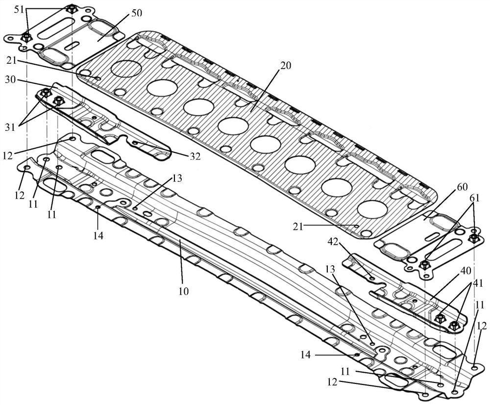
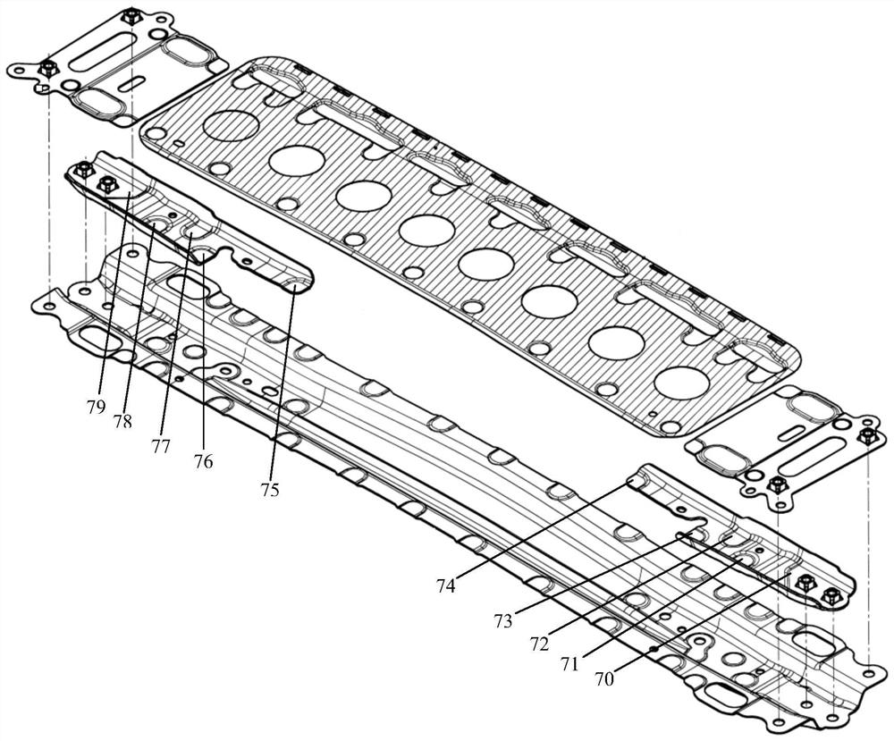
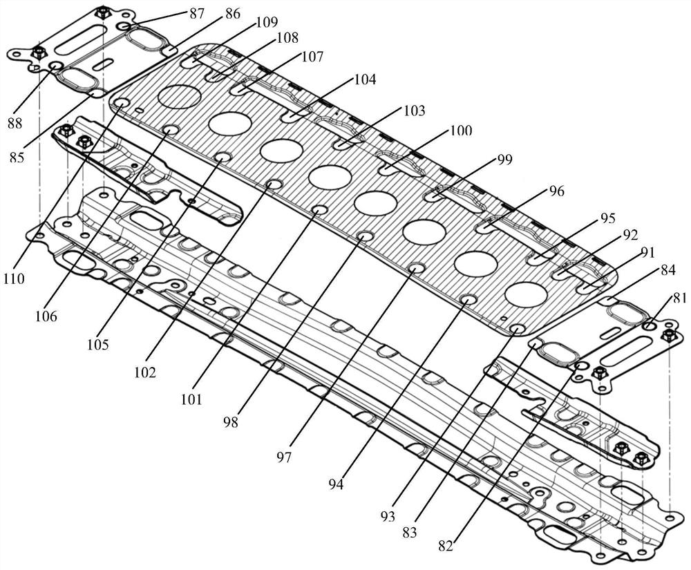
[0015] see Figure 1-Figure 3 , figure 1 It is an exploded view of the structure of the sliding sunroof frame of the embodiment of the present invention, figure 2 It is a schematic diagram of the layout of the welding points of the sliding sunroof frame according to the embodiment of the present invention, image 3 It is a schematic diagram of the arrangement of another welding spot of the sliding sunroof frame according to the embodiment of t...


PUM


Abstract

A welding process for a sliding sunroof frame, comprising steps: S1: welding first nuts on two first sliding sunroof frame plates to form two semi-finished products A; S2: welding second nuts on two second sliding sunroof frame plates Nuts to form two semi-finished products B; S3: Position the main frame of the sliding sunroof on the positioning tool; S4: Position the two semi-finished products A on the main frame of the sliding sunroof; S5: Arrange solder joints on the two semi-finished products A; S6 : Carry out spot welding according to the soldering point position, form semi-finished product C; S7: two semi-finished products B and sliding sunroof frame main board are positioned on semi-finished product C; S8: Solder spot position is arranged on two semi-finished products B and sliding sunroof frame main board; S9 : Spot welding is performed according to the position of the welding spot. The welding process of the sliding sunroof frame provided by the invention solves the technical problems of low precision and poor quality caused by the existing spot welding method, and achieves the technical effects of high spot welding precision, stable spot welding performance and guaranteed product quality.

Description

technical field [0001] The invention relates to the technical field of processing technology, in particular to a welding process of a sliding sunroof frame. Background technique [0002] Spot welding refers to the welding method that uses columnar electrodes to form solder joints between the contact surfaces of two overlapping workpieces. It is mainly used for welding stamping parts of thin plate members with a thickness of less than 4mm; when spot welding, pressurize first to make the workpiece Close contact, and then turn on the current, under the action of resistance heat, the contact part of the workpiece is melted, and a solder joint is formed after cooling. Today, with the progress of society and the improvement of living standards, the processing accuracy of parts in many industries is getting higher and higher. Especially in the automotive industry, many auto parts are more complicated and need to be made of multiple single products. Composite welding, in order to e...

Claims


Application Information

Patent Timeline
IPC IPC(8): B23K11/11
Inventor 寻璋
Owner 珠海市玛斯特汽车零部件有限公司
Why Eureka
Try Eureka