Laser welding machine and operation method thereof

A laser welding machine and laser head technology, applied in laser welding equipment, welding equipment, metal processing equipment, etc., can solve problems such as unreliable connection strength and fatigue resistance, affect the health of workers, and pollute the production environment. Improve welding quality, high work efficiency, and reduce pollution

Active Publication Date: 2021-11-05
ZHEJIANG IRON KING PRECISION HARDWARE MFG
View PDF7 Cites 0 Cited by
  • Summary
  • Abstract
  • Description
  • Claims
  • Application Information

AI Technical Summary

Problems solved by technology

[0002]Laser welding has been widely used in the current welding field due to its advantages such as high welding strength, high fatigue resistance, fast welding speed and wide range of weldable materials. , in the connection of multiple workpieces, the old processes such as riveting and spot welding have unreliable defects such as connection strength and fatigue strength, and the laser welding process has begun to enter this field. Compared with traditional welding, laser welding has a larger However, a large amount of harmful gas will still be produced. If it is not treated, it will easily lead to pollution of the production environment and affect the health of the staff. At the same time, in the laser welding process, welding along the circumference of the workpiece is not convenient enough, and in It is difficult to observe the weld seam during spot welding, and the welding accuracy is low, so it is necessary to make improvements

Method used


Image

  • Laser welding machine and operation method thereof
  • Laser welding machine and operation method thereof
  • Laser welding machine and operation method thereof

Examples


Embodiment 1

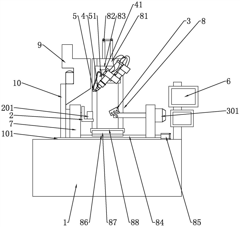
[0058] Such as Figure 1 to Figure 3 As shown, the embodiment of the present application provides a laser welding machine, which is characterized in that it includes:

[0059] A base 1, the upper surface of the base 1 is fixedly provided with a working table 101;

[0060] The left workpiece clamp 2, the sleeve rod 201 is arranged on the left workpiece clamp 2;

[0061] Right workpiece holder 3, said right workpiece holder 3 is provided with a clamping motor;

[0062] Laser head 4;

[0063] A microscopic camera 5, the surrounding of the microscopic camera 5 is provided with an illuminating lamp;

[0064] Display 6;

[0065]Wherein, the left workpiece clamp 2 and the right workpiece clamp 3 are all arranged on the left and right sides of the upper surface of the worktable 101 through the bracket 7, the left workpiece clamp 2 is connected with the bracket 7 in rotation, and the right workpiece clamp 3 is passed through the first The rotating motor 301 is rotationally connect...

Embodiment 2

[0068] In this embodiment, in addition to including the structural features of the foregoing embodiments, further said servo mechanism 8 also includes:

[0069] Z-axis support 81, the Z-axis support 81 is provided with a Z-axis driving motor 82 and a Z-axis slider 83;

[0070] X-axis support 84, the X-axis support 84 is provided with an X-axis driving motor 85 and an X-axis slider 86;

[0071] Y-axis support 87, the Y-axis support 87 is provided with a Y-axis drive motor and a Y-axis slider 88;

[0072] Wherein, the X-axis bracket 84 is fixedly arranged on the upper surface of the worktable 101, the X-axis slider 86 is slidably arranged on the X-axis bracket 84 and driven by the X-axis driving motor 85, and the Y-axis bracket 87 is fixedly arranged On the X-axis slider 86, the Y-axis slider 88 is slidably arranged on the Y-axis bracket 87 and driven by a Y-axis drive motor, and the Z-axis bracket 81 is fixedly arranged on the Y-axis slider 88, and the Z The shaft slider 83 i...

Embodiment 3

[0075] In this embodiment, in addition to including the structural features of the foregoing embodiments, it further includes:

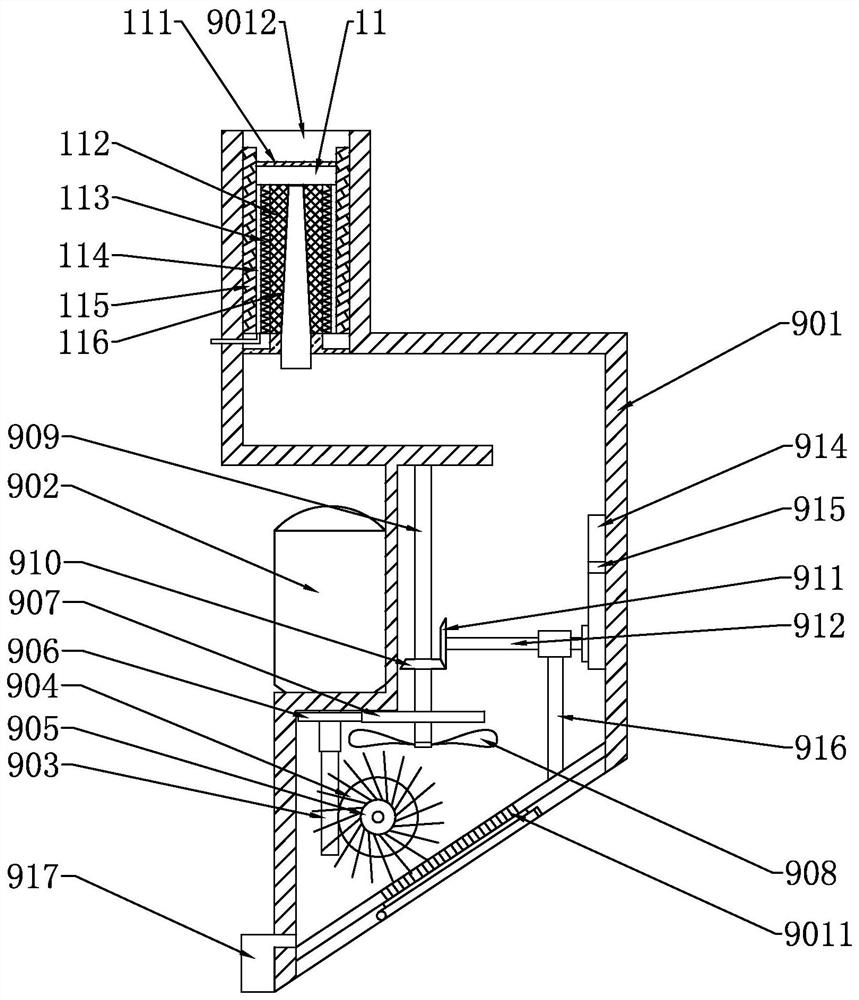
[0076] Flue gas treatment mechanism 9;

[0077] Mounting frame 10;

[0078] Wherein, the installation frame 10 is fixedly arranged on the upper surface of the working table 1, and the fume treatment mechanism 9 is fixedly arranged on the installation frame 10 and faces the welding area.

[0079] In the embodiment of the present application, the above-mentioned laser welding machine is adopted. During use, the fume processing mechanism can centrally process the fume generated during the welding process, reducing the phenomenon that the fume diffuses and pollutes the working environment, and reduces the workload. The health of personnel is damaged due to the harmful substances in the smoke.


PUM


Abstract

The invention relates to a laser welding machine and an operation method thereof. The laser welding machine comprises a base, a left workpiece clamp, a right workpiece clamp, a laser head, a microscopic camera and a display. A working table top is fixedly arranged on the upper surface of the base. A sleeve rod is arranged on the left workpiece clamp. A clamping motor is arranged on the right workpiece clamp. The left workpiece clamp and the right workpiece clamp are arranged on the left side and the right side of the upper surface of the working table top through supports, the left workpiece clamp is rotationally connected with the support, the right workpiece clamp is rotationally connected with the support through a first rotating motor, and the laser head is arranged on the working table top in a three-dimensional moving mode through a servo mechanism. The microscopic camera is fixedly arranged on the servo mechanism through a plastic steel pipe, and the display is electrically connected with the microscopic camera and is fixedly arranged on the upper surface of the base. Compared with the prior art, the laser welding machine has the advantages that the welding quality and spot welding precision of workpieces are improved, the phenomenon of pollution to the working environment is reduced, and the phenomenon that the physical health of workers is damaged is reduced.

Description

technical field [0001] The invention relates to a laser welding machine and its operating method. Background technique [0002] Due to the advantages of high welding strength, high fatigue strength, fast welding speed and wide range of weldable materials, laser welding has been widely used in the current welding field. In the connection of multiple workpieces, old methods such as riveting and spot welding Due to unreliable defects such as connection strength and fatigue strength, laser welding technology has begun to enter this field. Compared with traditional welding, although laser welding has a greater improvement, it will still produce a lot of harmful gases. If it is not treated If it is not, it will easily lead to pollution of the production environment and affect the health of the staff. At the same time, during the laser welding process, the welding along the circumference of the workpiece is not convenient enough, and it is difficult to observe the weld seam during ...

Claims


Application Information

Patent Timeline
IPC IPC(8): B23K26/16B23K26/21B23K26/70
CPCB23K26/21B23K26/702B23K26/16
Inventor 王达
Owner ZHEJIANG IRON KING PRECISION HARDWARE MFG
Why Eureka
Try Eureka