Design method of special-shaped electrode for resistance spot welding of stencil

A technology of resistance spot welding and design method, applied in the direction of CAD circuit design, electrode features, design optimization/simulation, etc., can solve the problems of poor quality consistency and low production efficiency of resistance spot welding, to ensure quality consistency and improve production. Efficiency and the effect of improving spot welding accuracy

Active Publication Date: 2021-09-21
SHANGHAI INST OF SPACE PROPULSION
View PDF3 Cites 0 Cited by
  • Summary
  • Abstract
  • Description
  • Claims
  • Application Information

AI Technical Summary

Problems solved by technology

[0006] In order to solve the problems of poor quality consistency and low production efficiency of resistance spot welding of stencil workpieces, a special-shaped spot welding electrode is designed, which can reduce human factors and improve spot welding accuracy and spot welding quality

Method used

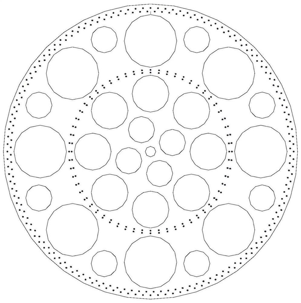
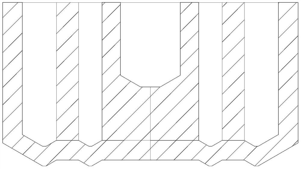
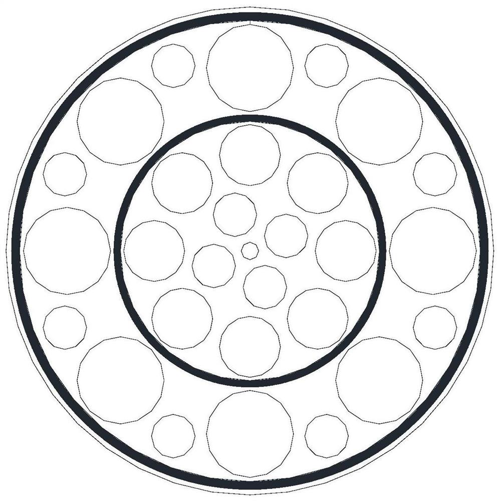

Image

  • Design method of special-shaped electrode for resistance spot welding of stencil
  • Design method of special-shaped electrode for resistance spot welding of stencil
  • Design method of special-shaped electrode for resistance spot welding of stencil

Examples


Embodiment Construction

[0032] The present invention will be described in detail below in conjunction with specific embodiments. The following examples will help those skilled in the art to further understand the present invention, but do not limit the present invention in any form. It should be noted that those skilled in the art can make several modifications and improvements without departing from the concept of the present invention. These all belong to the protection scope of the present invention.

[0033] The design method of the special-shaped electrode that is used for the grid resistance spot welding that the present invention provides specifically comprises the following steps:

[0034] S1. According to the mesh, plate material and thickness, select the electrode material suitable for the product. For aluminum alloys, generally use high-conductivity, medium-strength materials, such as pure copper or cadmium copper; for stainless steel and high-temperature alloys, generally use Materials ...


PUM

PropertyMeasurementUnit
electrical conductivityaaaaaaaaaa

Abstract

The invention discloses a method for designing a special-shaped electrode used for resistance spot welding of a mesh plate, comprising the following steps: 1. Selecting a suitable electrode material; 2. Drawing a preliminary two-dimensional map of the special-shaped electrode; 3. Establishing a three-dimensional geometric model; 4. , determine the boundary conditions; 5, use special analysis software to analyze the contact state between the electrode and the stencil workpiece, resistance heat and heat dissipation; 6, use the process test method for comparison; 7, determine the spot welding special-shaped electrode structure. The invention solves the problems of low production efficiency and unstable product quality in the spot welding of the stencil structure, and improves spot welding precision and weld seam quality. With the help of simulation analysis software and process test structure, the structure of special-shaped electrodes is optimized, the structure of special-shaped spot welding electrodes is determined, and the resistance spot welding of stencil structure products is finally realized. The invention can be applied to resistance spot welding of workpieces with screen structure, and also has broad application prospects in other resistance welding fields.

Description

technical field [0001] The invention belongs to a design method of a resistance welding electrode. In addition to the power supply system in resistance welding, the spot welding electrode is the most important component, which not only affects the current, pressure and heat conduction of the workpiece, but also directly affects the quality and efficiency of spot welding. The present invention specifically refers to the resistance spot welding of a flat material and a filter screen (hereinafter referred to as the screen workpiece), how to ensure the quality of the weld seam, improve the production efficiency, and reduce the product rejection rate. Background technique [0002] A monolithic rocket engine is a component that provides chemical power for a space vehicle and is the core component of a space propulsion system. There are a large number of mesh and plate connection structures inside the monolithic rocket engine, such as diaphragm parts, baffle parts and head parts. ...

Claims


Application Information

Patent Timeline
Patent Type & Authority Patents(China)
IPC IPC(8): G06F30/39G06F30/20B23K11/30
CPCB23K11/30G06F30/367G06F30/39
Inventor 田英超包海涛吴奇波宋凡张祎玲崔晓晟周杰
Owner SHANGHAI INST OF SPACE PROPULSION
Why Eureka
Try Eureka