
Disc spring type wedge-shaped hydraulic chuck for friction welding machine

A friction welding machine and disc spring technology, which is applied in the field of hydraulic chucks for friction welding machines, can solve the problems of workpiece and clamping jaw damage, occupying the inner space of the main shaft, low safety, etc. Reliable and high matching precision

Active Publication Date: 2014-04-09
江苏锐成机械有限公司
View PDF7 Cites 8 Cited by
  • Summary
  • Abstract
  • Description
  • Claims
  • Application Information

AI Technical Summary

Problems solved by technology

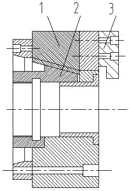
However, its disadvantages are that the clamping force is small, the clamping of the welding workpiece is not reliable, the workpiece is easy to slip, and the workpiece and the jaws are damaged; the clamping accuracy is not high, and the high-speed positioning of the workpiece cannot be achieved; it occupies the interior of the spindle Space: The rotary oil cylinder is connected to the main ram through the tie rod in the inner hole of the main shaft, and there is no space in the inner hole of the main shaft to install the axial positioning mechanism; the safety is not high: when the welding is working, the power is suddenly cut off or the oil cylinder is stuck, and the workpiece rotates at high speed It will fly out of the chuck, which is easy to become a major safety hazard

Method used


Image

  • Disc spring type wedge-shaped hydraulic chuck for friction welding machine
  • Disc spring type wedge-shaped hydraulic chuck for friction welding machine
  • Disc spring type wedge-shaped hydraulic chuck for friction welding machine

Examples


Embodiment Construction

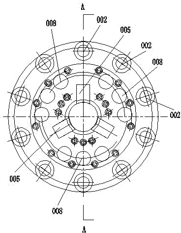
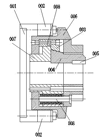
[0013] Disc spring wedge hydraulic chuck for friction welding machine, including main shaft 001, thrust cylinder 002 connected to the front end of main shaft 001, main ram 003, slave ram 004 and clamping block 005, the wedge-shaped inclined surface at the bottom of main ram 003 and The wedge-shaped slope on the top of the ram 004 engages, the clamp block 005 is installed on the front end of the ram 004, and a push seat 006 is provided. The push seat 006 is a cylindrical structure with a flange at the front end, and the center of the rear end of the push seat 006 A through hole is opened, and a flange 007 is fixedly connected in the through hole, and a disc spring structure 008 is arranged in the cylinder of the push seat 006, and the disc spring structure 008 is arranged above the flange side of the flange 007, The end of the disc spring structure 008 is fixed on the rear end of the cylinder body of the push seat 006, the front end of the disc spring structure 008 is connected ...


PUM


Abstract

The invention discloses a disc spring type wedge-shaped hydraulic chuck for a friction welding machine. The disc spring type wedge-shaped hydraulic chuck comprises a spindle, thrust cylinders, a main ram, an auxiliary ram and clamp blocks and is additionally provided with a thrust seat. The thrust cylinders, the main ram, the auxiliary ram and the clamp blocks are connected with the front end of the spindle, a wedge-shaped oblique plane of the bottom of the main ram is meshed with a wedge-shaped oblique plane of the top of the auxiliary ram, the clamp blocks are mounted at the front end of the auxiliary ram, the thrust seat is of a barrel-shaped structure, flange edges are arranged at the front end of the barrel-shaped structure, a through hole is formed in the center of the rear end of the thrust seat, a flange plate is fixedly connected into the through hole, disc spring structures are arranged in a barrel of the thrust seat and are arranged above flange edges of the flange plate, the tail ends of the disc spring structures are fixed to the inner rear end of the barrel of the thrust seat, the front ends of the disc spring structures are connected to certain portions of the main ram, the certain portions of the main ram are arranged in the barrel of the thrust seat, the auxiliary ram is arranged at the rear of the flange plate, and the thrust cylinders are correspondingly arranged at the rears of the flange edges of the thrust seat. The disc spring type wedge-shaped hydraulic chuck has the advantages that workpieces can be effectively prevented from flying out of the disc spring type wedge-shaped hydraulic chuck, clamping force can be greatly increased, and clamping damage to the workpieces can be effectively prevented.

Description

technical field [0001] The invention relates to the field of friction welding machine manufacturing, in particular to a hydraulic chuck for a friction welding machine. Background technique [0002] Most of the hydraulic chucks in the prior art adopt a pull rod in the main shaft, and the pull rod is driven by the rotary cylinder, and the pull rod drives the main ram 1 to move back and forth. On the slave ram 2, the slave ram moves up and down to realize the clamping and loosening of the workpiece. However, its disadvantages are that the clamping force is small, the clamping of the welding workpiece is not reliable, the workpiece is easy to slip, and the workpiece and the jaws are damaged; the clamping accuracy is not high, and the high-speed positioning of the workpiece cannot be achieved; it occupies the interior of the spindle Space: The rotary oil cylinder is connected to the main ram through the tie rod in the inner hole of the main shaft, and there is no space in the in...

Claims


Application Information

Patent Timeline
Patent Type & Authority Applications(China)
IPC IPC(8): B23K20/12B23K20/26B23K37/04
CPCB23K20/126
Inventor 赵艳会李伟强开明飞丁亚东
Owner 江苏锐成机械有限公司
Learn More