Highly-reliable fast locking mechanism

A locking mechanism and reliable technology, applied in the directions of transportation and packaging, vehicle parts, etc., can solve problems such as hidden safety hazards, poor natural environment protection ability, inconvenience, etc., to ensure locking and unlocking, reliable locking and unlocking, convenient and convenient. Effects of operations and inspections

Active Publication Date: 2014-04-09
BEIJING INST OF SPACE LAUNCH TECH +1
View PDF6 Cites 4 Cited by
  • Summary
  • Abstract
  • Description
  • Claims
  • Application Information

AI Technical Summary

Problems solved by technology

The locking mechanism used in the past relies on the self-locking friction angle of the lock block to lock the lock disc. When the designed frictional self-locking angle is close to or greater than the theoretical critical frictional self-locking angle, it is easy to unlock the phenomenon, and there is no prevention of unlocking after the frictional self-locking failure. Emergency measures cannot guarantee the reliable locking of the structure; the locking state of the structure is not obvious and cannot be corrected in time; the one-way operating device is very inconvenient during use; all parts of the structure have not been protected, which is harmful to nature Environmental protection is poor
The above problems lead to a great security risk in this structure

Method used


Image

  • Highly-reliable fast locking mechanism
  • Highly-reliable fast locking mechanism

Examples


Embodiment Construction

[0026] The present invention will be described in detail below in conjunction with the accompanying drawings and specific embodiments.

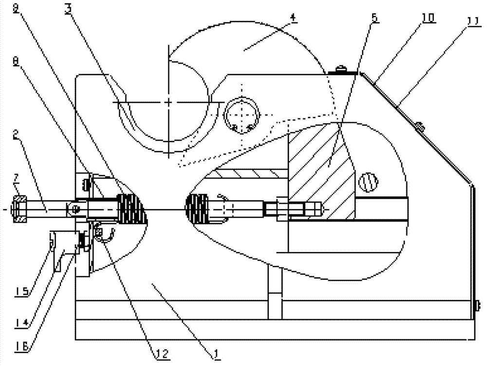
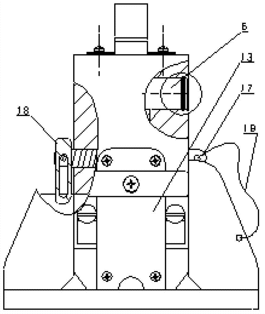
[0027] Such as figure 1 , figure 2 As shown, the highly reliable fast locking mechanism of the present invention includes a base 1, a push-pull rod 2, a copper sleeve 3, a lock plate 4, a lock block 5, a pin shaft 6, a handle 7, a sleeve 8, a return spring 9, a rubber Pad 10, dust cover 11, positioning strip 12, sealing plate 13, block 14, fixing bolt 15, spring 16, stop pin 17, stop piece 18, wire rope 19;

[0028] The lower part on the left side of the base 1 is a cavity, and the upper part is a semicircular hole. There are connecting holes for fixing bolts 15 and connecting holes for the sealing plate 13 at the end of the cavity, and there are pin shaft 6 mounting holes beside the semicircular hole; Cavity, the lower part is a slideway, there are stop pin 17 connection holes above the slideway, and there are 11 connection holes for the ...


PUM


Abstract

The invention belongs to technical field of vehicle chassis and particularly relates to a highly-reliable fast locking mechanism. The left lower portion of a base is provided with a cavity, and the left upper portion of the base is provided with a semi-circular hole. The right upper portion of the base is provided with cavity, and the right lower portion of the base is provided with a slideway. A push-pull rod is horizontally disposed in the left cavity of the base. A short rod is connected with the handle. A sleeve is sleeved outside of a long rod. The sleeve is welded with a seal plate and then connected to the opening of the left cavity of the base. A lock block is connected to the tip of the long rod. A copper bush is located in the semi-circular hole. A pin hole is formed in the middle of a lock plate, and the lower side of the lock plate is provided with friction self-locking face. The upper side of the lock block is a friction self-locking face corresponding to the friction self-locking face of the locking plate. The bottom of the lock block is located on the slideway of the base. A pin is located in the pin holes of the base and the lock plate. A retaining block, a fixing bolt and a spring are located at the opening of the left cavity of the base. The hook at one end of a return spring is mounted on the push-pull rod. The hook at the other end of the return spring is mounted on a positioning strip located at the left opening of the base. A stop pin tip hole is in pin joint with a stop plate pin and located above the slideway of the base, and the other end of a stop pin is connected with a steel wire rope.

Description

technical field [0001] The invention belongs to the technical field of special vehicle chassis, and in particular relates to a highly reliable fast locking mechanism. Background technique [0002] The locking mechanism is the main connection between the chassis and the launch tube, and it is used on every launch vehicle, and its reliability directly affects the safety of the launch tube. The locking mechanism used in the past relies on the self-locking friction angle of the lock block to lock the lock disc. When the designed frictional self-locking angle is close to or greater than the theoretical critical frictional self-locking angle, it is easy to unlock the phenomenon, and there is no prevention of unlocking after the frictional self-locking failure. Emergency measures cannot guarantee the reliable locking of the structure; the locking state of the structure is not obvious and cannot be corrected in time; the one-way operating device is very inconvenient during use; all ...

Claims


Application Information

Patent Timeline
Patent Type & Authority Applications(China)
IPC IPC(8): B60R11/00
Inventor 邓克军伊曙东杨献学陈喜宝赵焱明张生夏闽李玉龙孟博李谨闫惠东
Owner BEIJING INST OF SPACE LAUNCH TECH
Why Eureka
Try Eureka