Railway vehicle draw gear box

A rail vehicle and coupler box technology, which is applied in the direction of railway vehicle coupling accessories, railway car body parts, railway couplings, etc., can solve the problems of long distance from rescue positions, increase of coupler boxes, unfavorable installation and use, etc., and achieve reduction Small footprint, reduced height, increased height effect

Active Publication Date: 2014-04-09
CRRC QINGDAO SIFANG CO LTD
View PDF6 Cites 1 Cited by
  • Summary
  • Abstract
  • Description
  • Claims
  • Application Information

AI Technical Summary

Problems solved by technology

[0002] During the operation of rail vehicles, if a fault occurs, a rescue vehicle is required to rescue the faulty vehicle. Since the height of the coupler between the rescue vehicle and the faulty vehicle is generally inconsistent, it is necessary to use a transitional coupler for cooperation, and the storage of the transitional coupler is generally placed in the driver's seat. Indoor, but this method has the disadvantages of taking up a lot of space in the driver's cab, inconvenient transportation for line rescue, and a long distance from the rescue location.
The previously applied and published application number is 201220177928.3, which is called the patent of the coupler box of the EMU. After opening the door of the coupler box, pull the trolley to slide out along the slideway, and you can easily take the transitional coupler. However, there are some shortcomings in this patent. Because the rollers are set under the trolley, the height of the trolley is high, so it is necessary to place the transition For the coupler, the height of the coupler box needs to be increased, so that the coupler box takes up a lot of space, which is not conducive to installation and use in a narrow space under the car

Method used


Image

  • Railway vehicle draw gear box
  • Railway vehicle draw gear box
  • Railway vehicle draw gear box

Examples


Embodiment 1

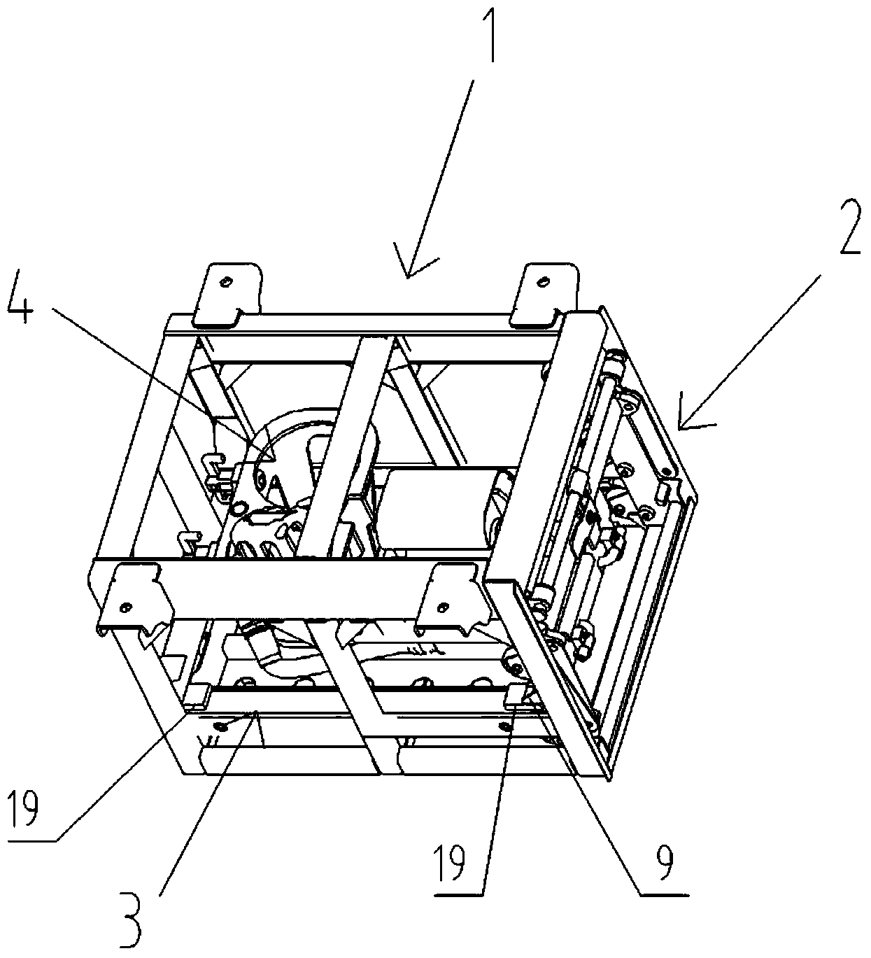
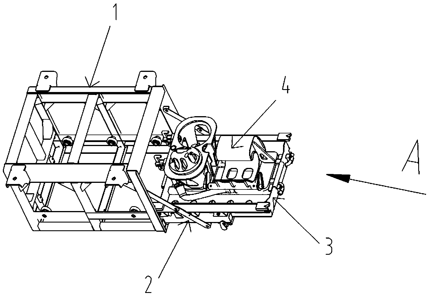
[0030] Such as figure 1 and figure 2 As shown, the rail vehicle coupler box includes a box body 1 and a box door 2 , and a trolley 3 is arranged inside the box body 1 , and the trolley 3 is used to place a transition coupler 4 .

[0031] Such as Figure 4 and Figure 5 As shown, the lower side of the box door 2 is hinged with the lower side of the box body 1, and the box door 2 can be rotated to open.

[0032] The box door 2 is composed of two vertical brackets 2a and a horizontal installation beam 2b. The lower sides of the two brackets 2a are respectively hinged with the lower side of the box body 1. The upper sides of the two brackets 2a are connected to the box body through a locking device. 1 is fixed, and the support 2a is a steel pipe with a square section.

[0033] Two connecting rods 5 are arranged between the casing 1 and each support 2a, and the two connecting rods 5 are connected in rotation, one end of one connecting rod 5 is fixedly connected with the casing...

Embodiment 2

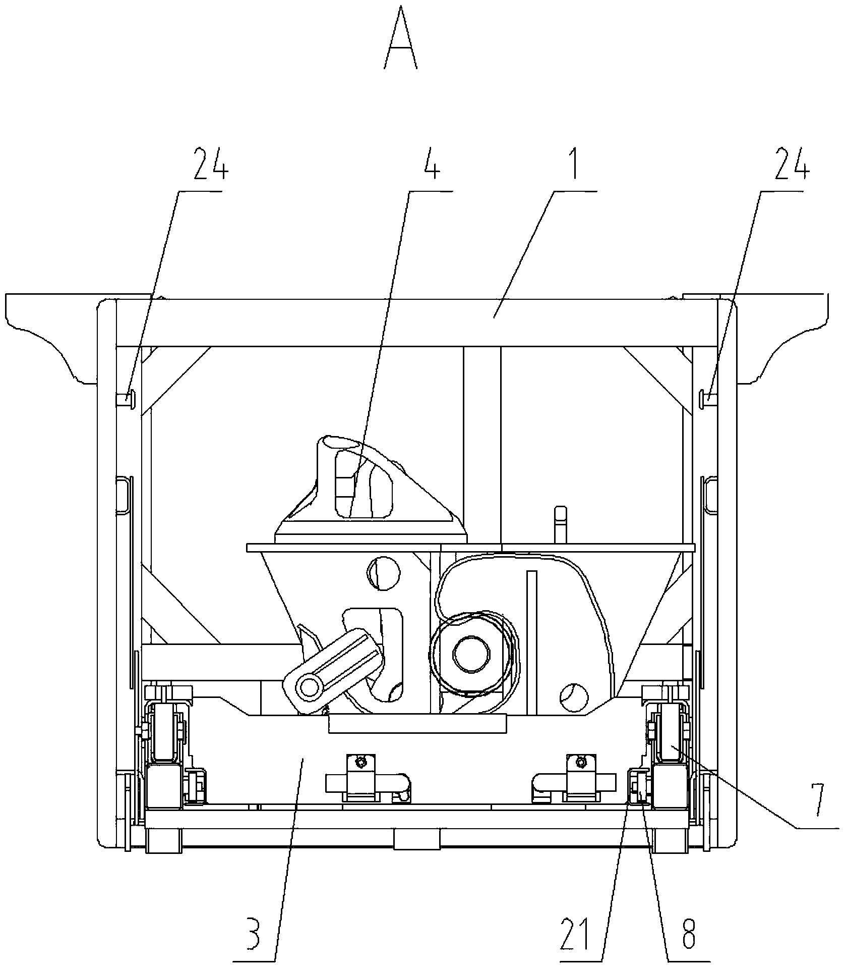
[0045] The difference from Embodiment 1 is that the structure of the pulley 8 is removed, and the door roller 7 is arranged at the position where the pulley 8 is located in Embodiment 1, that is, the door roller 7 is arranged on the opposite bracket wall of the two brackets 2a. Similarly, rollers 6 in the box are arranged on both side walls in the box body 1, and the position of the corresponding rollers 6 in the box is lower than that in embodiment 1, and the distance between the side walls of the box body 1 will be longer. So that after the chamber door 2 is opened, the inner roller 6 and the chamber door roller 7 can form a row of rollers aligned, so that the dolly can slide.

[0046] The trolley 3 removes the structure of the upper guide rail 20, and slides and cooperates with the inner roller 6 and the door roller 7 through the lower guide rail 21 whose cross-sectional shape is "C" shape, and the "C" shaped openings of the two lower guide rails 21 face to both sides respec...


PUM


Abstract

The invention relates to a railway vehicle draw gear box. The railway vehicle draw gear box comprises a box body and a box door, wherein the lower side of the box body is hinged to the lower side of the box door, a cart where a draw gear is placed is arranged in the box body, box inner idler wheels are arranged in the box body, box door idler wheels are arranged on the box door, the box inner idler wheels and the box door idler wheels form two rows of idler wheels located on the two sides of the cart after the box door is opened, and guide rails are arranged on the two sides of the cart and are in sliding fit with the two rows of idler wheels. By arranging the idler wheels on the two sides of the cart, the height of the cart is reduced, the heights of components which the cart can be loaded with are increased, and space occupied by the draw gear box is reduced. After the box door is opened, the cart can slide along the idler wheels of the box door, the end of the cart can slide out of the box door, and therefore the distance of travel of the cart is increased. Due to the arrangement of the double layers of guide rails, the cart will not topple when the box door slides upwards.

Description

technical field [0001] The invention relates to a box body, in particular to a rail vehicle coupler box. Background technique [0002] During the operation of rail vehicles, if a fault occurs, a rescue vehicle is required to rescue the faulty vehicle. Since the height of the coupler between the rescue vehicle and the faulty vehicle is generally inconsistent, it is necessary to use a transitional coupler for cooperation, and the storage of the transitional coupler is generally placed in the driver's seat. Indoors, but this method has the disadvantages of taking up a large space in the driver's cab, inconvenient transportation for line rescue, and a long distance from the rescue location. The previously applied and published application number is 201220177928.3, which is called the patent of the coupler box of the EMU. After opening the door of the coupler box, pull the trolley to slide out along the slideway, and you can easily take the transitional coupler. However, there a...

Claims


Application Information

Patent Timeline
IPC IPC(8): B61G7/00B61G9/22
Inventor 单永林鄢桂珍宋红李丰李树海李宏
Owner CRRC QINGDAO SIFANG CO LTD
Why Eureka
Try Eureka