Hollow beamless floor system structure and construction method thereof
A hollow floor and construction method technology, applied in the direction of floors, building components, building structures, etc., can solve the problems of increasing the weight of floors or floors, increasing construction costs, and complicated procedures, so as to simplify construction procedures, reduce weight, The effect of simple construction process
- Summary
- Abstract
- Description
- Claims
- Application Information
AI Technical Summary
Problems solved by technology
Method used
Image
Examples
Embodiment approach 1
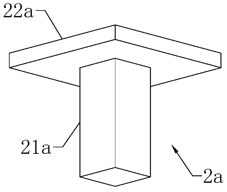
[0036] Implementation Mode 1: see image 3 , the supporting column unit 2a includes a column body 21a and a column cap 22a, the column cap 22a is arranged on the upper end of the column body 21a, the upper end of the column cap 22a is arranged on the lower end surface of the floor 1, and the column cap The lower end of 22a is connected to the upper end of the column 21a, and the lower end of the column 21a is set on the ground. The horizontal cross-sectional area of the column cap 22a is larger than the horizontal cross-sectional area of the column body 21a. The floor 1 transmits the force received in the longitudinal direction to the column cap 22a, and the column cap 22a then indirectly transmits the force to the column body 21a, and the column body 21a finally transmits the force to the ground, and the supporting column unit 2a plays a role in supporting the floor 1 role. The column cap 22a concentrates and transmits the force received by the large area on the upper p...
Embodiment approach 2
[0039] Implementation mode two: see Figure 4 , the supporting column unit 2b includes a column body 21b and a column cap 22b, the column cap 22b is funnel-shaped with a large upper end and a small lower end, and the upper end surface of the column cap 22b is connected to the lower end surface of the floor 1, The lower end surface of the column cap 22b is connected to the upper end of the column body 21b, and the horizontal cross-sectional area of the column cap 22b is larger than that of the column body 21b. The funnel-shaped column cap 22b not only meets the stress requirements of the building, but also has a beautiful appearance.
[0040] In order to improve the effect of force transmission, the side surface of the lower end of the column cap 22b and the side surface of the upper end of the column body 21b make a smooth transition. The smooth transition structure also makes the support column unit 2b more beautiful.
Embodiment approach 3
[0041] Embodiment 3 (not shown in the figure): the supporting column unit 2 includes a column, the upper end of the column is set on the lower end surface of the floor 1 , and the lower end of the column is set on the ground. In fact, the column cap is not necessary for the support column unit 2, and the support column unit 2 can also play the role of supporting the floor 1 by only including columns, as long as the size meets the requirements of construction mechanics.
[0042]In the embodiment of the present invention, the mandrel 13 can be a hollow tube, an inflatable mandrel or a wooden mandrel, and the inflatable mandrel is an air bag of rubber material. Mandrel 13 also can select the mandrel of other materials, for example bamboo mould. Its density is smaller than that of concrete, which can ensure that the weight of the floor 1 is sufficiently light. If the inflatable mandrel is selected, a through hole for extracting the air bag of the mandrel can also be reserved on t...
PUM
 Abstract
Description
Claims
Application Information
 - R&D Engineer
- R&D Manager
- IP Professional
- Industry Leading Data Capabilities
- Powerful AI technology
- Patent DNA Extraction
Browse by: Latest US Patents, China's latest patents, Technical Efficacy Thesaurus, Application Domain, Technology Topic, Popular Technical Reports.
© 2024 PatSnap. All rights reserved.Legal|Privacy policy|Modern Slavery Act Transparency Statement|Sitemap|About US| Contact US: help@patsnap.com


