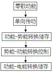
Potential energy storage type device for collecting scattered energy
An energy collection and storage technology, applied in the field of energy collection, can solve the problems of low conversion efficiency, difficulty in reaching the speed required for power generation, discontinuity, etc., and achieve the effect of improving energy utilization
- Summary
- Abstract
- Description
- Claims
- Application Information
AI Technical Summary
Problems solved by technology
Method used
Image

Examples
Embodiment 1
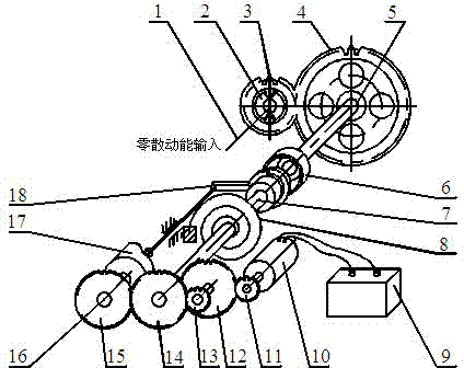
[0017] Such as figure 2 As shown, the one-way transmission system includes an input shaft 1, a friction ratchet 2, a driving gear 3 and a driven gear 4, a front half shaft 5, a clutch 6 and a rear half shaft 7, and the driving gear 3 and the driven gear 4 are a pair of reduction gears. There are two types of kinetic energy-potential energy conversion and storage units. In this embodiment, the elastic potential energy storage unit includes a scroll spring 8 ; the energy conversion control system includes a timing gear 15 , a cylindrical cam 17 and a clutch fork 18 . The electric energy conversion and storage system includes speed-up gears 11 , 12 , 13 and 14 , as well as a generator 10 and a storage battery 9 .
[0018] The working mode of this embodiment is a process of alternating cycles of energy storage and power generation.
[0019] In the energy storage stage, the clutch 6 is closed, and the scattered kinetic energy generated by the door shaft or fitness equipment is in...
Embodiment 2
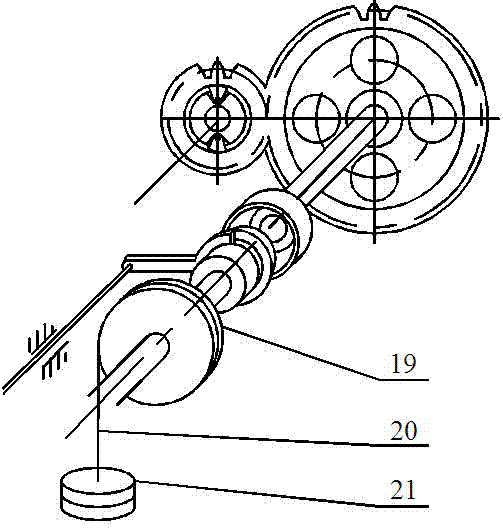
[0023] Such as image 3 as shown,
[0024] The difference from Embodiment 1 is that Embodiment 2 uses a gravitational potential energy storage unit, including a drum 19 , a wire rope 20 and a counterweight 21 . All the other structures are basically the same as in Example 1.
[0025] The difference between the work of embodiment 2 and embodiment 1 is: in the energy storage stage, the clutch 6 is closed, and the scattered kinetic energy generated by the door shaft or fitness equipment is input by the energy input shaft 1, and is transmitted through the one-way transmission system to drive the rear half shaft 7 unidirectional rotation, soft rope 20 adopts steel wire rope, makes counterweight 21 rise, realizes kinetic energy-potential energy conversion.
[0026] In the power generation stage, the potential energy stored in the potential energy storage unit reaches the set upper limit, the cam 17 pushes the clutch fork 18 to separate the clutch 6, and the rear half shaft 7 conne...
PUM
 Abstract
Description
Claims
Application Information
 - Generate Ideas
- Intellectual Property
- Life Sciences
- Materials
- Tech Scout
- Unparalleled Data Quality
- Higher Quality Content
- 60% Fewer Hallucinations
Browse by: Latest US Patents, China's latest patents, Technical Efficacy Thesaurus, Application Domain, Technology Topic, Popular Technical Reports.
© 2025 PatSnap. All rights reserved.Legal|Privacy policy|Modern Slavery Act Transparency Statement|Sitemap|About US| Contact US: help@patsnap.com