Driving device and servo motor device

A technology of servo motor and drive device, applied in the direction of electromechanical devices, electrical components, mechanical equipment, etc., can solve problems such as assembly errors and inability to use servo motor devices

Active Publication Date: 2014-04-09
FUTABA CORPORATION
View PDF9 Cites 3 Cited by
  • Summary
  • Abstract
  • Description
  • Claims
  • Application Information

AI Technical Summary

Problems solved by technology

[0022] As described in Patent Document 1, when the casing of the servo motor device is provided with a scale, although it is known that the neutral position of the output shaft makes it easy to install the servo horn, since both the output shaft and the servo horn are existing Due to the structure of the device, there will still be assembly errors caused by misreading the scale
[0023] In addition, as described in Patent Document 2, the fitting portion of the output shaft of the servo motor device and the servo shim is made into a special shape to prevent errors in the mounting position of the servo shim. Only in such a state that a dedicated servo shim can be installed
Therefore, existing servo shims cannot be used for this servo motor device

Method used


Image

  • Driving device and servo motor device
  • Driving device and servo motor device
  • Driving device and servo motor device

Examples


Embodiment 1

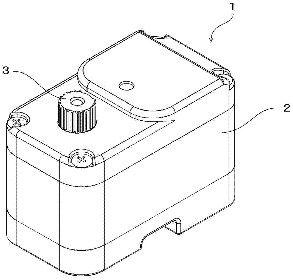
[0060] figure 1 It is a figure which shows the appearance of the casing 2 of the servomotor apparatus 1 of Example 1 of this invention.

[0061] In this figure, since the inside of the casing 2 of the servo motor device 1 is the same as that of a conventional servo motor device, description thereof will be omitted.

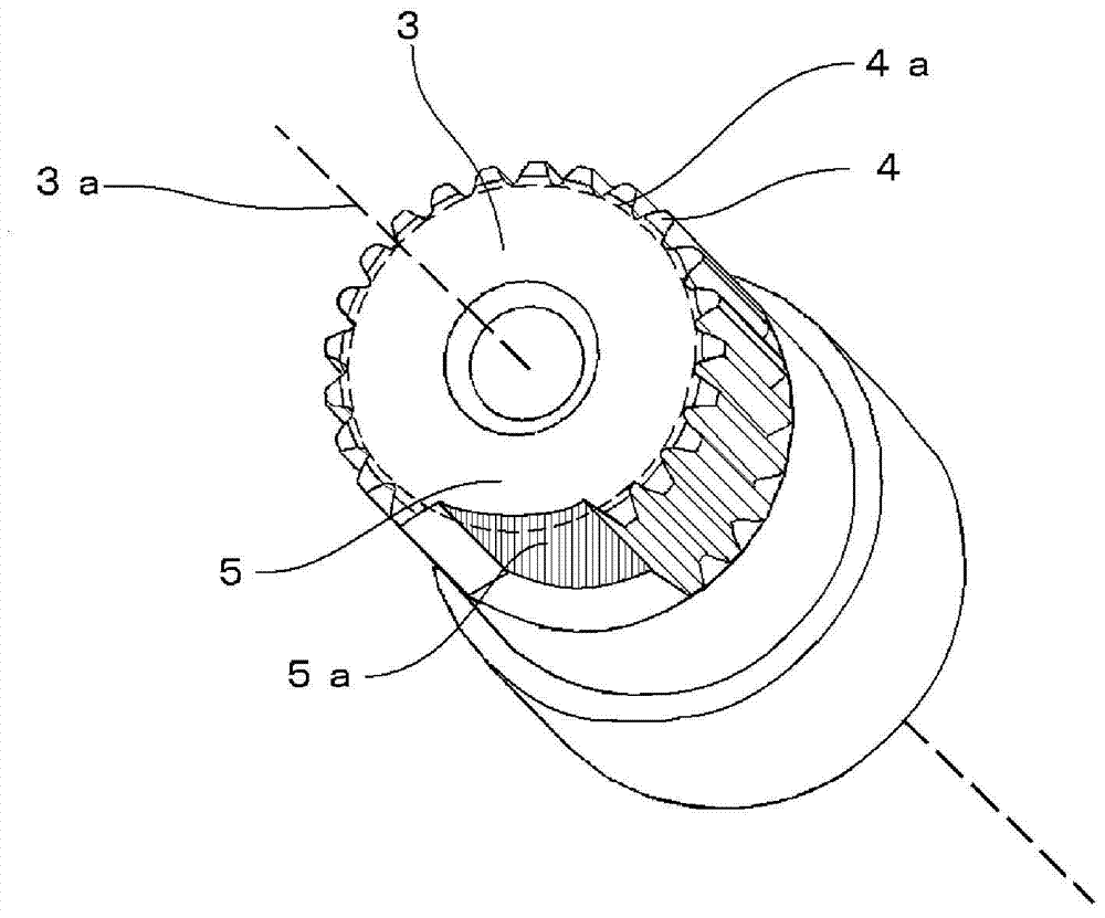
[0062] figure 2 It is a figure which removed the output shaft 3 of the servomotor apparatus 1 of Example 1 from the housing 2, and showed with a part of shape omitted.

[0063] The servo motor device 1 according to Embodiment 1 of the present invention has a rotating output shaft 3 , and a sawtooth portion 4 and a tooth-missing portion 5 are provided on a surface parallel to the rotation axis 3 a of the output shaft 3 . The output shaft 3 of the servo motor device 1 can also be an output shaft that rotates within a predetermined angle range. Furthermore, the serrated portion 4 is provided with concavities and convexities having a certain period, that is, serr...

Embodiment 2

[0080] Image 6 It is a figure which removed the output shaft 13 of the servomotor apparatus which concerns on Example 2 of this invention from a housing, and showed a part shape abbreviate|omitted. Since the structure of the servo motor device other than the output shaft 13 is the same as that of the first embodiment, description thereof will be omitted.

[0081] A plurality of, for example, three sawtooth portions 14a, 14b and a plurality of, for example, three tooth-missing portions 15 are provided on a surface parallel to the rotation axis of the output shaft 13 of the servo motor device.

[0082] The output shaft 13 can be fitted with a dedicated servo shim having a fitting portion not shown that fits at a specific position to form a drive device.

[0083] At this time, if the serrated parts 14a, 14b and the tooth-missing part 15 are evenly divided, even if it is a dedicated servo pad, the installation position of the servo pad will not be specified. The zigzag portions...

Embodiment 3

[0087] Figure 7 It is a figure which removed the output shaft 30 of the servomotor apparatus of Example 3 of this invention from a housing, and a part shape is abbreviate|omitted and shown. Since the structure of the servo motor device other than the output shaft 30 is the same as that of the first embodiment, description thereof will be omitted.

[0088] The output shaft 30 is provided with a missing-tooth portion position display portion for displaying the missing-tooth portion 32 as a mark 33 . The installation of the servo horn becomes easier by providing the mark 33 . In addition, like the other embodiments, the drive device is constituted by the servo motor device of the third embodiment and the servo shim attached to the output shaft 30 at a specific position.

[0089] The mark 33 is for emphasizing the missing tooth part 32 with respect to the upper surface 31 of the output shaft 30, and is provided so that the upper surface part of the tooth missing part 32 may be ...


PUM


Abstract

The invention provides a driving device and a servo motor device. An output shaft (3) of a servo motor device is provided with a zigzag-shaped part (4) and a teeth-missing part (5). The zigzag-shaped part (4) is provided with concave parts and convex parts periodically. The length of the teeth-missing part (5) from a rotating shaft (3a) to the teeth-missing part (5) is shorter than the length from the rotating shaft (3a) to a root circle (4a) of the zigzag-shaped part (4). By adopting the structure, the special servo gasket irons embedded with the special position of the output shaft (3) and the conventional servo gasket irons disposed at any angles and positions on the output shaft (3) can be disposed on the output shaft (3).

Description

technical field [0001] The present invention relates to a servo motor device for controlling the manipulated body, in particular to an output shaft of the servo motor device that transmits the output of the motor to the movable part of the manipulated body, and a drive with a servo motor device and a servo horn device. Background technique [0002] In the radio control system for remote control of the manipulated body in the distance, as the existing executive device for driving and controlling the manipulated body according to the instructions of the operator, a small DC motor (hereinafter referred to as is a motor) is a servo motor device that drives the source. [0003] Figure 10 is a cross-sectional view schematically showing an example of a drive device including the servo motor device and the servo shim. [0004] The servo motor unit 20 has an approximately rectangular parallelepiped casing 21 . A motor 22 and a plurality of reduction gears (Gears) 23 are housed in...

Claims


Application Information

Patent Timeline
Patent Type & Authority Applications(China)
IPC IPC(8): F16D1/06F16D1/112H02K7/10
Inventor 植村千寻
Owner FUTABA CORPORATION
Why Eureka
Try Eureka