Parallel shift mechanism for transfer case

A shifting mechanism, parallel technology, applied in the field of parallel shifting mechanism, can solve the problems of inflexible shifting, poor reliability, easy to drop gears, etc., achieve ingenious and compact structure, short axial dimension, and ensure reliability Effect

Active Publication Date: 2016-01-27
BEIJING INST OF SPACE LAUNCH TECH +1
View PDF5 Cites 0 Cited by
  • Summary
  • Abstract
  • Description
  • Claims
  • Application Information

AI Technical Summary

Problems solved by technology

[0002] At present, most of the shifting mechanisms of domestic transfer cases are single and simple in structure, poor in reliability, and easy to lose gears; in addition, because the air source cannot be absolutely dry, the inner wall of the cylinder is generally rusted and corroded, resulting in inflexible shifting , shifting gears is prone to failure after a long time

Method used


Image

  • Parallel shift mechanism for transfer case
  • Parallel shift mechanism for transfer case
  • Parallel shift mechanism for transfer case

Examples


Embodiment Construction

[0026] The present invention will be described in detail below in conjunction with the accompanying drawings and specific embodiments.

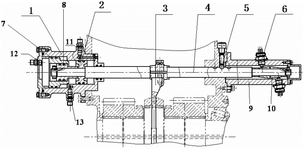
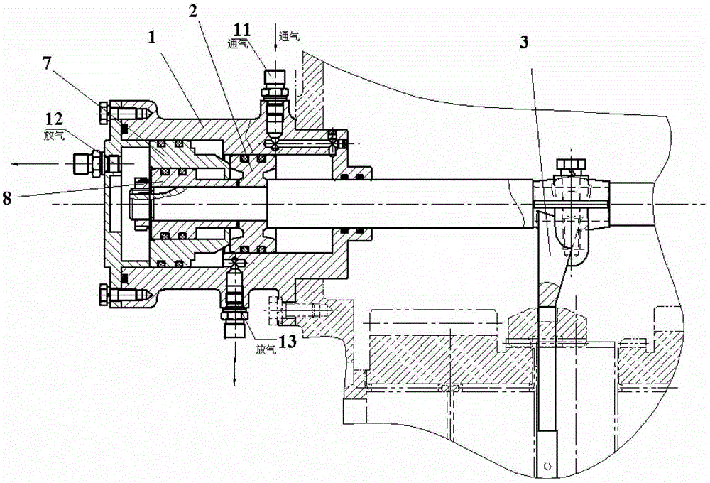
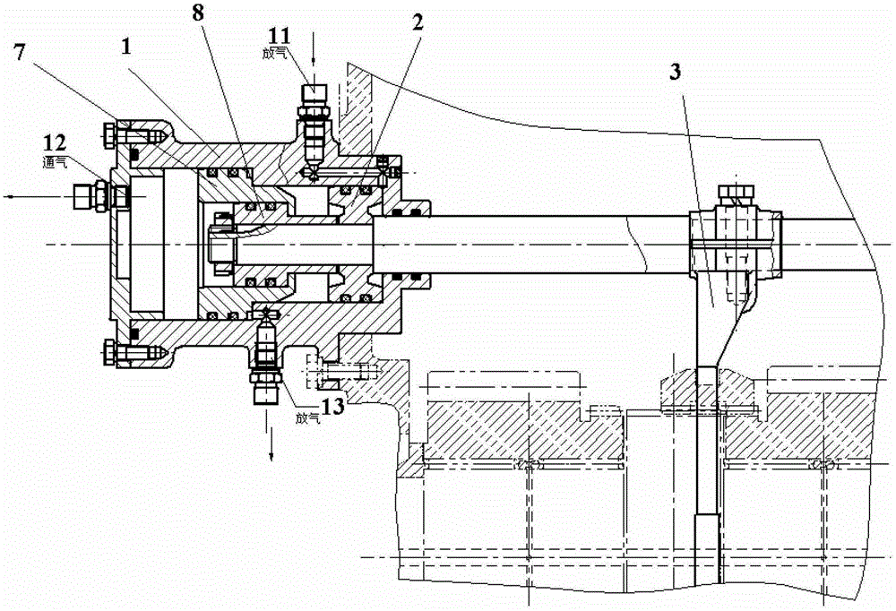
[0027] Such as figure 1 As shown, the parallel shift mechanism of the transfer case of the present invention includes a cylinder body 1, a piston A2, a shift fork 3, a shift shaft 4, a locking mechanism 5, a signal switch 6, a piston B7, a piston C8, a cylinder cover 9. Taper sleeve 10, I port 11, II port 12, III port 13;

[0028] The cylinder 1 is fixed on the housing of the deceleration mechanism, the piston A2, the piston B7, and the piston C8 are arranged in the inner cavity of the cylinder 1, and can move freely in the cylinder 1, and the piston A2 is located on the right side of the cylinder 1 , piston C8 is located on the left side of piston A2, and piston B7 is connected to piston C8 through a spigot; one end of shift shaft 4 is fixed with piston A2, piston B7, and piston C8 through nuts, and the other end of shift shaft 4 is inserte...


PUM


Abstract

The invention belongs to the technical field of mechanical transmission and particularly relates to a parallel gear shifting mechanism of a transfer case. A piston A, a piston B and a piston C are disposed in a cylinder body and can move freely. The piston A is located on the right of the cylinder body. The piston C is located on the left of the piston A. The piston B is connected with the piston C through a spigot. One end of a gear shifting shaft is fixed to the piston A, the piston B and the piston C. The other end of the gear shifting shaft is inserted into the inner hole of a cylinder cover and integrally fixed with a conical sleeve. A signal switch is disposed on the cylinder cover. A shifting fork is located in the middle of the gear shifting shaft and integrally fixed with the gear shifting shaft. A locking mechanism is disposed on the shifting block and in the middle of the cylinder cover. Three inflating inlets I, II and III respectively corresponding to the piston A, the piston B and the piston C are formed in the cylinder body. When inflation is performed respectively through the inflating inlets I, II and III, the corresponding pistons are pushed to move by air pressure, the gear shifting shaft and the shifting fork are then driven to move, and the contact of the signal switch contacts with the conical sleeve to give out corresponding indications when corresponding gears are reached.

Description

technical field [0001] The invention belongs to the technical field of mechanical transmission, and in particular relates to a parallel shift mechanism of a transfer case. Background technique [0002] At present, most of the shifting mechanisms of domestic transfer cases are single and simple in structure, poor in reliability, and easy to lose gears; in addition, because the air source cannot be absolutely dry, the inner wall of the cylinder is generally rusted and corroded, resulting in inflexible shifting , Shifting gears is prone to failure after a long time. Contents of the invention [0003] The purpose of the present invention is to provide a parallel shift mechanism of transfer case with good operability and high reliability, so as to meet the requirements of high reliability, convenience and excellent usability of transfer case for special vehicle chassis. gearshift needs. [0004] In order to achieve the above object, the technical scheme adopted in the present...

Claims


Application Information

Patent Timeline
Patent Type & Authority Patents(China)
IPC IPC(8): F16H61/26F16H61/02F16H63/34
CPCF16H61/30F16H63/34F16H63/42F16H2061/301
Inventor 赵娟单红波葛铠赵焱明张斌张磊黄宏伟
Owner BEIJING INST OF SPACE LAUNCH TECH
Why Eureka
Try Eureka