Valve seat structure of track ball valve

A technology of valve seat and ball valve, which is applied in the field of seat structure of orbital valves. It can solve the problems of time-consuming and laborious, cumbersome sealing surface, and can not meet the long-term stable sealing of valves, and achieve zero leakage and convenient maintenance.

Active Publication Date: 2014-04-09
SHANGHAI SHENTONG ENTERPRISE DEV
View PDF7 Cites 3 Cited by
  • Summary
  • Abstract
  • Description
  • Claims
  • Application Information

AI Technical Summary

Problems solved by technology

Most of the valve seats of existing track valves are inlaid on the valve body through interference fit, or welded on the valve body. When the sealing surface is damaged and needs to be repaired, it is quite cumbersome, time-consuming and laborious, and basically difficult to achieve.
Moreover, the existing valve seat only adopts one sealing method, that is, hard seal or soft seal, which cannot well meet the needs of long-term stable sealing of valves in the production process.

Method used


Image

  • Valve seat structure of track ball valve

Examples


Embodiment Construction

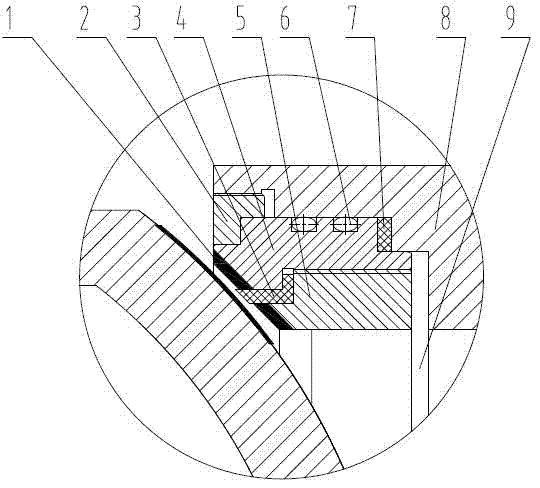
[0013] Such as figure 1 As shown, a valve seat structure of an orbital ball valve includes a valve seat. The valve seat includes an upper valve seat 4 and a lower valve seat 5. The contact surfaces between the upper valve seat 4 and the lower valve seat 5 are all stepped surfaces. A soft sealing ring 3 is provided between the inner stepped surfaces of the valve seat, and the soft sealing ring 3 protrudes outward from the upper and lower valve seat sealing surfaces 1, and the outer stepped surfaces of the upper and lower valve seats are fixedly connected by threads. The axial contact end surface of the upper valve seat 4 and the valve body 8 is a stepped surface, and a flexible graphite sealing ring 7 is arranged between the lower end surface of the stepped surface and the valve body, and the upper end surface of the stepped surface is flush with the end surface of the lower valve seat 5, and There is a compression gap 9 between the upper valve seat 4 and the valve body 8, and ...


PUM


Abstract

The invention provides a valve seat structure of a track ball valve which comprises a valve seat. The valve seat comprises an upper valve seat and a lower valve seat. The contact face of each of the upper valve seat and the lower valve seat is a stepped face. A soft seal ring is disposed between the stepped faces, close to the inner side, of the upper valve seat and the lower valve seat. The soft seal ring protrudes out of the seal faces of the upper valve seat and the lower valve seat. The stepped faces, close to the outer side, of the upper valve seat and the lower valve seat are fixedly connected through threads. The axial contact end face of the valve body of the upper valve seat is a stepped face, a flexible graphite seal ring is disposed between the low end face of the stepped face and the valve body, the high end face of the stepped face is parallel with the end face of the lower valve seat, and a compression gap is reserved between the high end face of the stepped face and the valve body. A groove is formed in the radial contact face of the upper valve seat and the valve body. An O-shaped ring is disposed in the groove. The upper valve seat is fixedly connected with the valve body through a pressing ring. Hard alloy is disposed at the seal face of the upper valve seat and the lower valve seat by means of surfacing. The valve seat structure adopting composite sealing is good in airtightness, zero leakage is achieved, and mounting and maintenance convenience are achieved by using the pressing ring to fix the valve seat structure.

Description

technical field [0001] The invention relates to a valve seat, in particular to a valve seat structure of an orbital valve. Background technique [0002] Orbital ball valves are widely used in petroleum, chemical, electric power and other industries as regulating and cutting devices. The valve seat of the existing orbital valve is mostly inlaid on the valve body through interference fit, or welded on the valve body. When the sealing surface is damaged and needs to be repaired, it is quite cumbersome, time-consuming and laborious, and basically difficult to achieve. Moreover, the existing valve seat only adopts one sealing method, that is, a hard seal or a soft seal, which cannot well meet the need for long-term stable sealing of the valve in the production process. Contents of the invention [0003] In order to overcome the above-mentioned shortcomings of the existing orbital ball valve seat, the present invention provides an orbital ball valve seat structure, which has go...

Claims


Application Information

Patent Timeline
Patent Type & Authority Applications(China)
IPC IPC(8): F16K5/20
CPCF16K5/0673F16K5/0689F16K5/08F16K25/005
Inventor 唐春荣陈志勇卢海
Owner SHANGHAI SHENTONG ENTERPRISE DEV
Why Eureka
Try Eureka