Water and electricity independent dual-core electromagnetic induction fast heating water heater

An electromagnetic induction and magnetic induction technology, applied in the field of quick-heating electromagnetic induction water heaters, can solve the problems of user protection limitations, uneven water temperature in the water tank, slow water temperature rise, etc., and achieve the effects of low noise, fast heating, and uniform water temperature

Active Publication Date: 2016-07-06
珠海市传奇电子有限公司
View PDF8 Cites 0 Cited by
  • Summary
  • Abstract
  • Description
  • Claims
  • Application Information

AI Technical Summary

Problems solved by technology

Even if various protection measures are added in the future, they are only remedial measures after the event, and there are limitations in the protection of users, and safety accidents still occur from time to time
[0006] In addition, the traditional electric water heater generally inserts an electric heating tube from one end of the water tank to heat the water, which causes the water at one end of the water tank to heat up faster, while the water at the other end without the electric heating tube heats up slowly, so the water temperature inside the tank is uneven.

Method used


Image

  • Water and electricity independent dual-core electromagnetic induction fast heating water heater
  • Water and electricity independent dual-core electromagnetic induction fast heating water heater
  • Water and electricity independent dual-core electromagnetic induction fast heating water heater

Examples


Embodiment Construction

[0045] Various embodiments of the present invention will be described in detail below, examples of which are illustrated with reference to the accompanying drawings and described below. While the invention will be described in conjunction with exemplary embodiments, it should be understood that the invention is not limited to these exemplary embodiments. On the contrary, the present invention includes not only these embodiments but also various modifications and improvements.

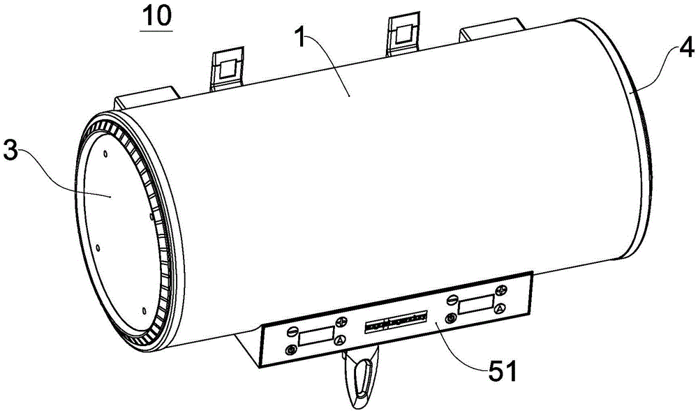
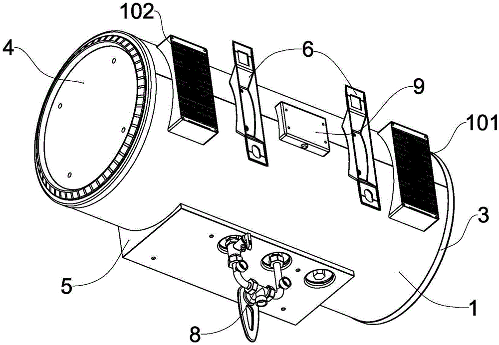
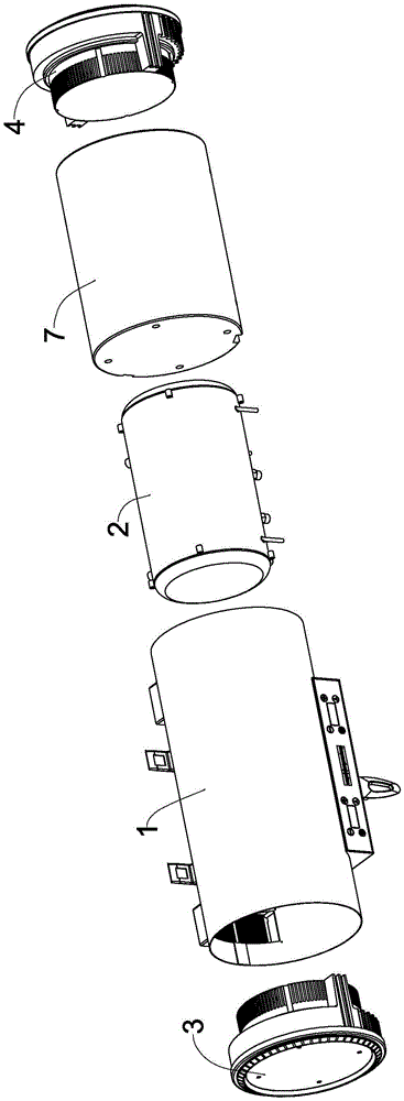
[0046] Figure 1 to Figure 5 Shows an instant water heater 10 according to an embodiment of the present invention, which includes a casing 1, a water tank 2, a first electromagnetic heating unit 3, a second electromagnetic heating unit 4, a control unit 5, etc., and the casing 1 is roughly cylindrical , the water tank 2 is located inside the shell 1, and the outer surface of the water tank 2 is covered with a heat-insulating layer 7. The heat-insulating layer 7 adopts the integral foaming polyurethane ...


PUM


Abstract

The invention provides a dicaryon electromagnetic induction instant water heater with water and electricity independent. The dicaryon electromagnetic induction instant water heater comprises an outer shell, a water tank, a first electromagnetic heating unit and a second electromagnetic heating unit, and the first electromagnetic heating unit and the second electromagnetic heating unit are arranged on the two end sides of the water tank. The water tank comprises a tank shell, a first electromagnetic induction self-heating plate and a second electromagnetic induction self-heating plate, the first electromagnetic induction self-heating plate and the second electromagnetic induction self-heating plate are arranged at the two ends of the tank shell, a water inlet pipe, a guide pipe and a water outlet pipe are arranged in a water storage chamber of the water tank, a water inlet end at the bottom of the tank shell is communicated with the guide pipe through the water inlet pipe, a water outlet end at the bottom of the tank shell is communicated with the water storage chamber through the water outlet pipe, heat exchange holes are formed in the positions, tightly adjacent to the surface of the first electromagnetic induction self-heating plate and the surface of the second electromagnetic induction self-heating plate, on the guide pipe, and the guide pipe is communicated with the water storage chamber through the heat exchange holes. The water of the water heater flows to the surfaces of the electromagnetic induction self-heating plates at the two ends of the water tank through the guide pipe, absorbs the heat on the surfaces of the two electromagnetic induction self-heating plates in time and then returns to a water outlet of the water tank. Therefore, heating is fast, efficiency is high, and water temperature in the water tank is even.

Description

technical field [0001] The invention relates to the field of electric water heaters, in particular to a fast-heating electromagnetic induction water heater. Background technique [0002] Existing electric water heaters generally adopt the resistance heating principle to heat water. The electric heating elements generally used are also called electric heating tubes. The electric heating tube is to wrap the electric heating wire (usually an electric heating material such as tungsten wire) with a high temperature resistant insulating material such as ceramics, and then use stainless steel tubes or aluminum tubes and copper tubes on the outside. The metal tube is wrapped to prevent the ceramic from bursting. When working, the electric heating tube is placed in the water tank, and the electric heating tube directly heats the water in the water tank through heat conduction. [0003] If a small-power electric heating tube is used to soak in a large-volume water tank, and the heat ...

Claims


Application Information

Patent Timeline
Patent Type & Authority Patents(China)
IPC IPC(8): F24H1/18F24H9/18F24H9/00F24H9/02
Inventor 康雪涛
Owner 珠海市传奇电子有限公司
Why Eureka
Try Eureka