Laser pulse contrast ratio measurement device based on optical limiting

A laser pulse and measuring device technology, applied in the direction of instruments, etc., can solve problems such as limited dynamic range, achieve the effects of flexible and convenient adjustment, improved detectability, and improved recording time range

Inactive Publication Date: 2014-04-09
LASER FUSION RES CENT CHINA ACAD OF ENG PHYSICS
View PDF4 Cites 9 Cited by
  • Summary
  • Abstract
  • Description
  • Claims
  • Application Information

AI Technical Summary

Problems solved by technology

Due to the limitations of the detection equipment, the dynamic range of these device tests is limited

Method used


Image

  • Laser pulse contrast ratio measurement device based on optical limiting

Examples


Embodiment 1

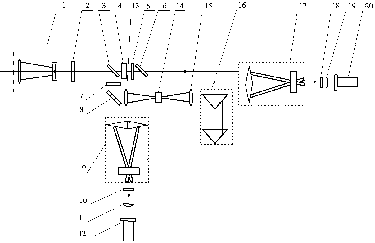
[0016] figure 1 It is a schematic diagram of the optical path of the laser pulse contrast measurement device based on optical clipping of the present invention. figure 1 In the laser pulse contrast measurement device based on optical limiting of the present invention, in the measurement device, a collimating mirror 1, an attenuation sheet 2, and a beam splitter I3 are sequentially placed in the incident direction of the high-power laser pulse; the incident pulse light The beam splitter I3 is divided into transmitted light and reflected light. On the transmitted light path of the beam splitter I3, a frequency doubling crystal 4, a filter 5, and a beam splitter II6 are arranged in sequence, and on the reflected light path of the beam splitter I3, a Half-wave plate 7, beam splitter III 8; the transmitted light of beam splitter I3 passes frequency doubling crystal 4 to generate frequency doubled light, and the frequency doubled light passes through filter 5 to filter out the remai...


PUM


Abstract

The invention provides a laser pulse contrast ratio measurement device based on optical limiting. In the laser pulse contrast ratio measurement device, a collimating mirror, an attenuation piece and a beam splitter I are sequentially placed in the high-power laser pulse incidence direction, a frequency doubling crystal, a filtering piece and a beam splitter II are sequentially arranged on a transmission light path of the beam splitter I, a half wavelength plate and a beam splitter III are sequentially arranged on a reflection light path of the beam splitter I, a convex lens I, a limiter, a convex lens II and a delay regulator are sequentially arranged on the reflection light path of the beam splitter III, frequency doubling light generated by the frequency doubling crystal is divided into a transmission portion and a reflection portion through the beam splitter II, the transmission portion and the reflection portion are parallel to transmission fundamental frequency light from the beam splitter III and reflection fundamental frequency light from the beam splitter III respectively and enter two third-order correlators respectively, correlated signals generated by the two third-order correlators are collected through a CCD, and finally, data are processed through a computer. The laser pulse contrast ratio measurement device is flexible and convenient to adjust and wide in test dynamic range.

Description

technical field [0001] The invention belongs to the technical field of high-power laser testing, and in particular relates to a laser pulse contrast measuring device based on optical limiting for high-power laser testing. Background technique [0002] In various experiments of strong radiation sources, advanced gamma light sources and strong radiation sources hitting solid targets, the gasified substances and plasma generated by the pre-pulse will change the state of the target substances, thereby affecting the action process and even changing the action mechanism , the contrast becomes the bottleneck restricting many experiments. Without a sufficiently high laser pulse contrast, the desired experimental results cannot be achieved. The development of ultra-short pulse technology urgently requires a single-shot pulse contrast test. The Chinese utility model patent (Patent No. ZL 2010 2 0690649.8) named "Laser Pulse Waveform Measuring Device" discloses a method that simultan...

Claims


Application Information

Patent Timeline
Patent Type & Authority Applications(China)
IPC IPC(8): G01J11/00
Inventor 夏彦文孙志红邓颖刘华董军彭志涛
Owner LASER FUSION RES CENT CHINA ACAD OF ENG PHYSICS
Why Eureka
Try Eureka