Pump head on oil-free air compressor

A technology of air compressors and pump heads, which is applied to pump components, mechanical equipment, variable capacity pump components, etc., and can solve the problem of shaking of cooling pipes, easy breakage of the connection between cooling pipes and cylinders, and affecting the service life of pump heads, etc. problem, to achieve the effect of improving the service life

Active Publication Date: 2017-11-21
浙江博高机电科技有限公司
View PDF16 Cites 0 Cited by
  • Summary
  • Abstract
  • Description
  • Claims
  • Application Information

AI Technical Summary

Problems solved by technology

At present, the direct-coupled oil-free air compressor below 2kw uses two cylinders and two crankshafts to work at the same time to generate compressed air. To get a higher pressure, two-stage compression is required (the air compressed by the first-stage compression cylinder is passed into the second-stage compression cylinder for two-stage compression). Because of the two-stage compression, the pump head will A lot of heat is generated, so the two cylinders on some pump heads on the market are connected by winding cooling pipes, so that the air can be cooled when passing through the cooling pipes, but the traditional cooling pipe winding method, When the high-power motor drives the pump head to work for a long time, due to the two-stage compression, the power of the pump head increases, the cooling pipe will shake greatly, and the connection between the cooling pipe and the cylinder is prone to breakage, thus It will affect the service life of the pump head; if the pump head on the traditional air compressor needs to perform two-stage compression, the diameter of one of the cylinders is usually reduced to achieve two-stage compression (the gas is completely compressed in the first-stage compression cylinder) Later, since the diameter of the 2-stage compression cylinder is smaller than that of the 1-stage compression cylinder, the gas can be compressed in 2 stages after entering the 2-stage compression cylinder), but the diameter of the cylinder itself is relatively small. If the diameter of one of the cylinders is used to achieve two-stage compression, the compression ratio of the two cylinders cannot be well controlled.

Method used


Image

  • Pump head on oil-free air compressor
  • Pump head on oil-free air compressor

Examples


Embodiment Construction

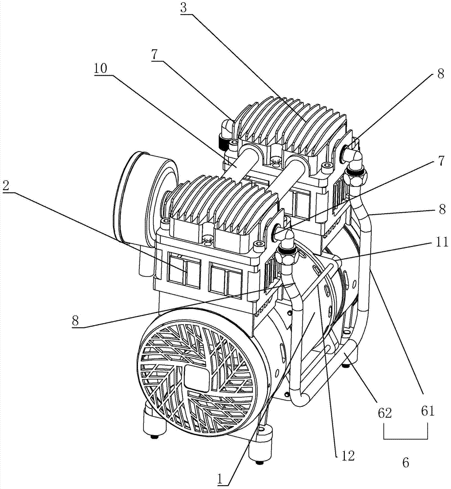
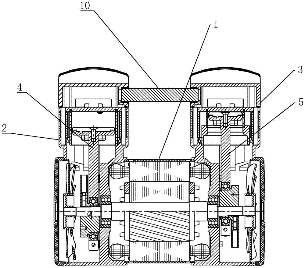
[0010] refer to Figure 1 to Figure 2 The embodiment of the pump head on the oil-free air compressor of the present invention will be further described.

[0011] A pump head on an oil-free air compressor, comprising a motor 1, a first-stage compression cylinder 2 and a second-stage compression cylinder 3, the first-stage compression cylinder 2 is provided with a first crankshaft 4, and the second-stage compression cylinder 3 is There is a second crankshaft 5, the first crankshaft 4 and the second crankshaft 5 are respectively sleeved on both ends of the main shaft of the motor 1, and a cooling pipe 6 is communicated between the first-stage compression cylinder 2 and the second-stage compression cylinder 3, and the first-stage compression The air outlet 7 is provided on the cylinder 2 and the second-stage compression cylinder 3, and the air inlet 8 is also provided on the second-stage compression cylinder 3. The two ends of the cooling pipe 6 are connected to the air inlet 8 an...


PUM


Abstract

The invention discloses a pump head on an air oil-less compressor. A first bent axle is arranged in a first-stage compression cylinder. A second bent axle is arranged in a second-stage compression cylinder. The first bent axle and the second bent axle are arranged at the two ends of a motor main shaft in a sleeving mode respectively. A cooling pipe is communicated between the first-stage compression cylinder and the second-stage compression cylinder, and the two ends of the cooling pipe are connected with an air inlet and an air outlet of the first-stage compression cylinder respectively. The diameter of the first-stage compression cylinder is larger than that of the second-stage compression cylinder. The eccentric distance of the first bent axle is larger than that of the second bent axle. The cooling pipe is U-shaped and arranged on the same side of the first-stage compression cylinder and the second-stage compression cylinder. As the cooling pipe is wound in a U shape and on the same side of the pump head, the cooling pipe can not extend too long. When a large-power motor works, the cooling pipe does not vibrate seriously, so that the cracking phenomenon at the joints between the cooling pipe and the cylinders is avoided, and the service life of the pump head is prolonged.

Description

technical field [0001] The invention relates to an oil-free direct-coupled air compressor, more specifically, it relates to a pump head on an oil-free air compressor. Background technique [0002] Air compressor is the basic product of industrial modernization. It is often said that electricity and automation have the meaning of full pneumatic, and air compressor is to provide air source power. It is the core equipment of the pneumatic system and the main body of the electromechanical air source device. It is a device that converts the mechanical energy of the motor into gas pressure energy, and it is a gas pressure generating device for compressed air. At present, the direct-coupled oil-free air compressor below 2kw uses two cylinders and two crankshafts to work at the same time to generate compressed air. To get a higher pressure, two-stage compression is required (the air compressed by the first-stage compression cylinder is passed into the second-stage compression cylin...

Claims


Application Information

Patent Timeline
Patent Type & Authority Patents(China)
IPC IPC(8): F04B39/00F04B39/06F04B39/12
Inventor 周春金银康
Owner 浙江博高机电科技有限公司
Why Eureka
Try Eureka