
Operating device for inflating cabinet

An operating device and a technology for an inflatable cabinet, applied in the field of inflatable cabinets, can solve the problems of not the best choice, high manufacturing cost, complex structure, etc.

Inactive Publication Date: 2014-04-09
TAIPINGYANG POWER EQUIP GROUP CHANGZHOU +1
View PDF5 Cites 4 Cited by
  • Summary
  • Abstract
  • Description
  • Claims
  • Application Information

AI Technical Summary

Problems solved by technology

[0002] At present, the operating device is one of the core components in the inflatable cabinet. It controls the orderly action of the isolating switch and the grounding switch to realize the segmentation and grounding functions of the main circuit. The common design idea of ​​the operating device is to choose a spring (coil spring or pressure Spring) operating mechanism, but this type of mechanism is large in size, complex in structure, and high in manufacturing cost. Generally speaking, it is not the best choice. Moreover, most electric operating devices are based on the principle of worm gear transmission structure and mechanical clutch. The output angle The control depends on the joint action of the micro switch installed on the circular track of the turbine movement and the mechanical clutch. The electric operating mechanism with this principle structure has high requirements on the installation position of the micro switch and the characteristics of the micro switch changing with temperature. At the same time, Due to the mechanical wear of the mechanical clutch, it is difficult to ensure long-term accurate control of the output angle of this mechanism

Method used


Image

  • Operating device for inflating cabinet
  • Operating device for inflating cabinet
  • Operating device for inflating cabinet

Examples


Embodiment Construction

[0016] In order to make the content of the present invention easier to understand clearly, the present invention will be described in further detail below according to specific embodiments in conjunction with the accompanying drawings,

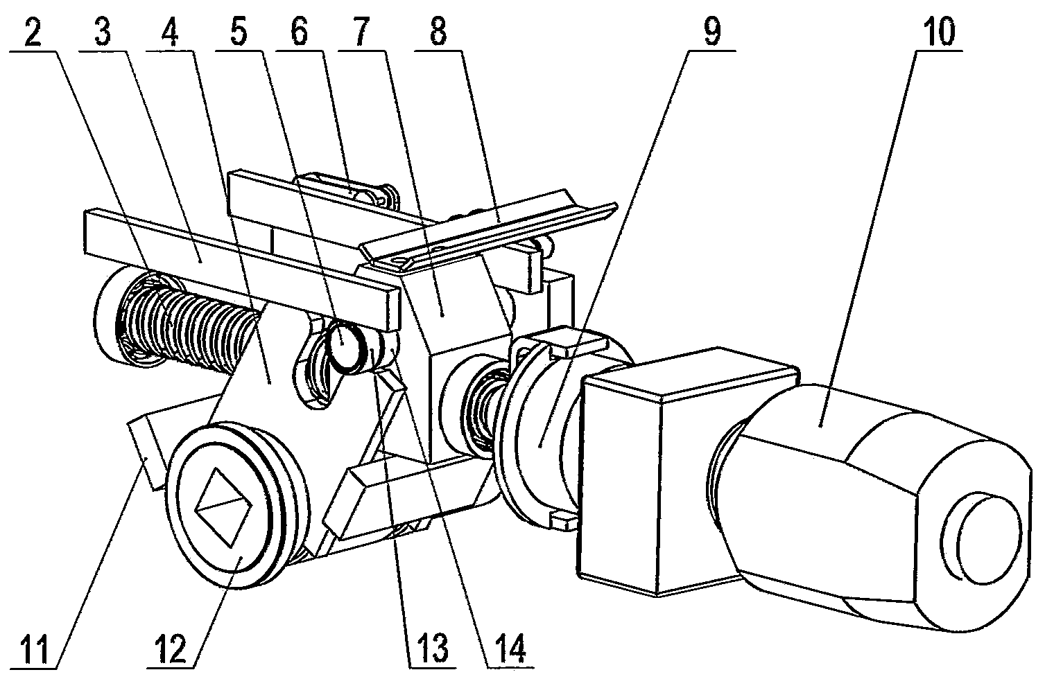
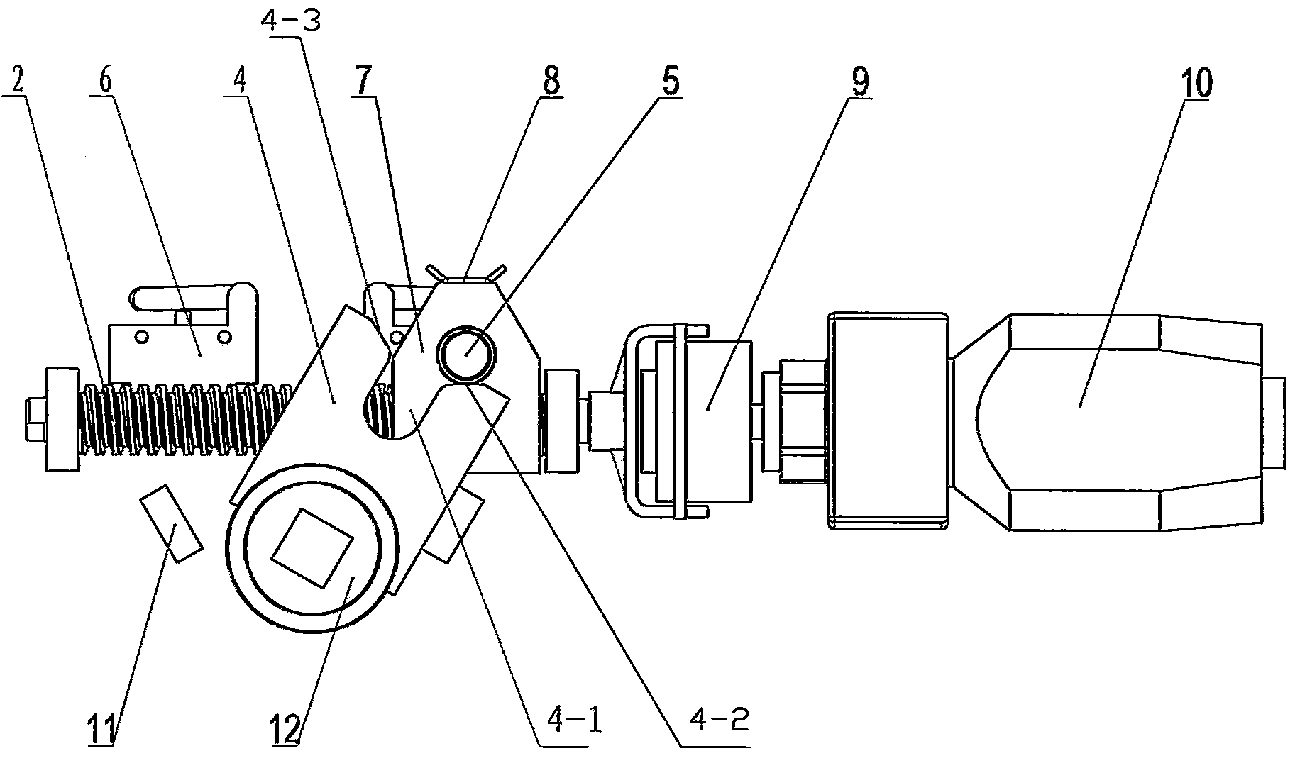
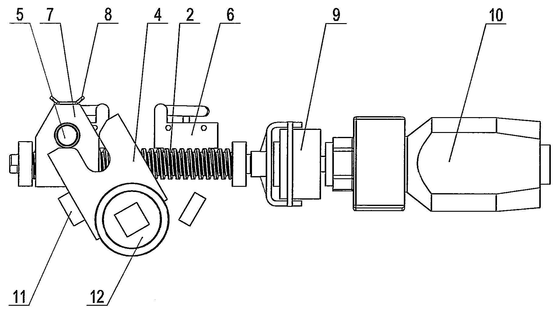
[0017] Such as Figure 1~3 As shown, an operating device for an inflatable cabinet includes a motor assembly 10, a drive shaft 5, an output rotating shaft 12, a drive plate 4, a lead screw 2 and a nut 7 that is threaded on the lead screw 2 and when the lead screw When the bar 2 rotates, the nut 7 moves axially along the screw 2. The drive shaft 5 is mounted on the nut 7. The drive plate 4 is fixedly connected to the output rotating shaft 12. The motor assembly 10 drives the screw 2 to rotate. The plate 4 is provided with a drive slot 4-1 that matches the drive shaft 5. When the output rotation shaft 12 is within the output rotation angle range, the drive shaft 5 is located in the drive slot 4-1. When the output rotation shaft 12 leaves the out...


PUM


Abstract

The invention discloses an operating device for an inflating cabinet. The operating device for the inflating cabinet comprises a motor assembly, a driving shaft, an output rotating shaft, a driving plate, a screw rod, a nut and a guide assembly, wherein the nut is connected on the screw rod through threads, the guide assembly is used for enabling the nut to move in the axial direction of the screw rod when the screw rod rotates, the driving shaft is mounted on the nut, the driving plate is fixedly connected on the output rotating shaft, the motor assembly drives the screw rod to rotate, and a driving groove matched with the driving shaft is formed in the driving plate. When the output rotating shaft is located in an output rotating angle range, the driving shaft is located in the driving groove, and when the output rotating shaft leaves the output rotating angle range, the driving shaft is separated from the driving groove. The motor assembly is further in control connection with two micro switches which control the motor assembly to be started and stopped respectively, the nut is provided with a pressing plate matched with the micro switches, and the two micro switches are arranged at the head end and the tail end of the travel of the nut respectively. According to the operating device for the inflating cabinet, accurate control over output rotating angles can be guaranteed, and movements are stable.

Description

technical field [0001] The invention relates to an operating device for an inflatable cabinet, belonging to the technical field of inflatable cabinets. Background technique [0002] At present, the operating device is one of the core components in the inflatable cabinet. It controls the orderly action of the isolating switch and the grounding switch to realize the segmentation and grounding functions of the main circuit. The common design idea of ​​the operating device is to choose a spring (coil spring or pressure Spring) operating mechanism, but this type of mechanism is large in size, complex in structure, and high in manufacturing cost. Generally speaking, it is not the best choice. Moreover, most electric operating devices are based on the principle of worm gear transmission structure and mechanical clutch. The output angle The control depends on the joint action of the micro switch installed on the circular track of the turbine movement and the mechanical clutch. The e...

Claims


Application Information

Patent Timeline
IPC IPC(8): H01H3/26
Inventor 高旻东赵树生杨志刚
Owner TAIPINGYANG POWER EQUIP GROUP CHANGZHOU
Learn More