External-heating energy-saving and environment friendly rotary carbonization furnace

A rotary carbonization furnace, energy-saving and environmental protection technology, applied in the chemical industry, sustainable manufacturing/processing, climate sustainability, etc., can solve the problem of high wear and breakage rate, difficult to control the final temperature of carbonization, serious material surface ablation, etc. problems, to achieve the effects of easy control of the heating rate, environmental protection, and low material accumulation

Inactive Publication Date: 2011-06-15
淮北市协力重型机器有限责任公司 +1
View PDF9 Cites 15 Cited by
  • Summary
  • Abstract
  • Description
  • Claims
  • Application Information

AI Technical Summary

Problems solved by technology

[0005] The carbonization converter in the prior art is an internal heating single-cylinder rotary furnace. Under the same production capacity, the material accumulates relatively high in the furnace cylinder, the throwing height is relatively high, the material is heated unevenly, and the rate of wear and breakage is high, and the yield of carbonized products is low. In addition, the direct contact between the heating medium and the raw material to be carbonized during the working process of this rotary furnace will cause the volatile gas combustion flame produced by carbonization to directly contact the raw material. , the outer surface of the carbonized material produces an aperture, which makes it difficult for the next step of the activation process; at the same time, this kind of equipment also needs an external heat source, which consumes a lot of energy

Method used


Image

  • External-heating energy-saving and environment friendly rotary carbonization furnace
  • External-heating energy-saving and environment friendly rotary carbonization furnace
  • External-heating energy-saving and environment friendly rotary carbonization furnace

Examples


Embodiment Construction

[0011] The present invention will be described below in conjunction with the accompanying drawings and embodiments.

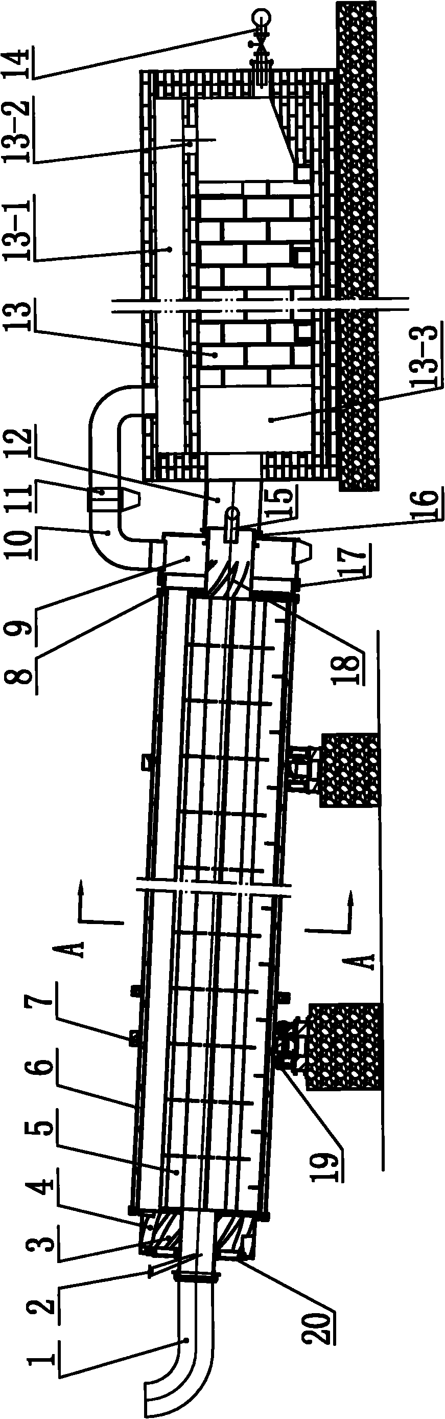
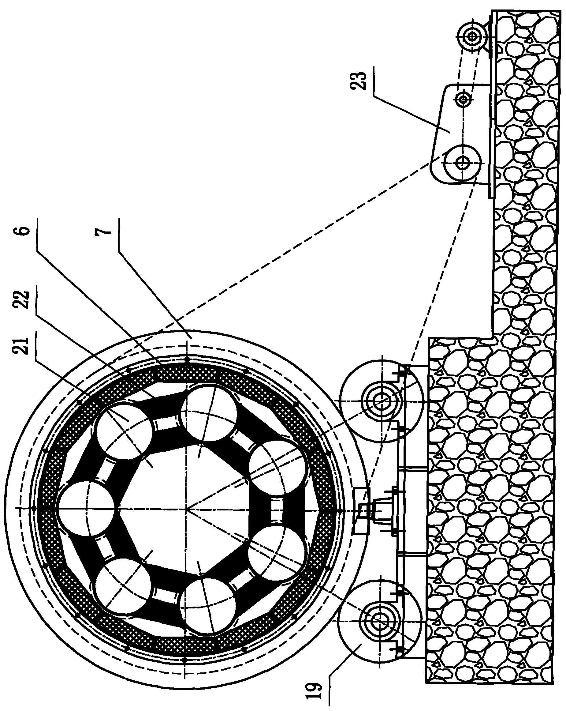
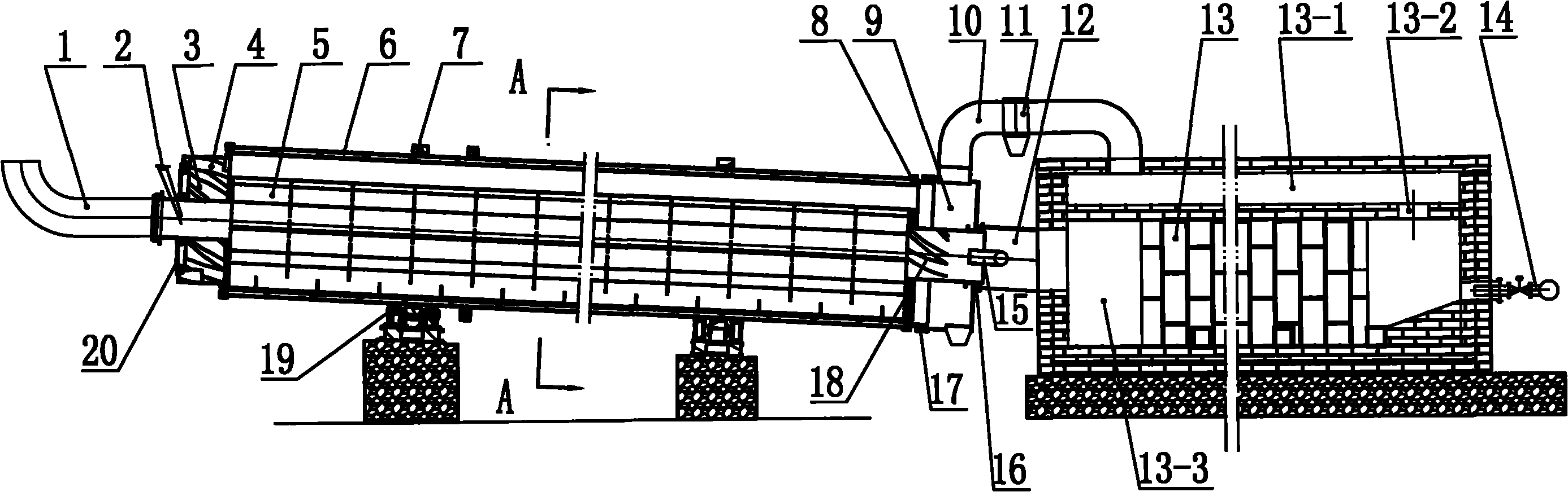
[0012] like figure 1 , figure 2 As shown, the present invention comprises feeding bin 3, furnace body 5, furnace shell 6, discharging bin 9, volatile matter pipeline 10, combustion chamber 13, high temperature flue gas pipe 12, tail gas exhaust pipe 1, driving mechanism 23; Furnace Body 5 is made up of at least three independent material passages 21 (commonly referred to as product passages in the industry), and the cross section of material passage 21 is a closed annular section, and the annular section can be circular, elliptical, with rounded corners or without circles. The circular sections such as the polygon of corner, are connected with rib plate 22 between material channel 21. The furnace body 5 is placed in the furnace shell 6, and the end is fixed on the furnace shell 6 to form a rotating body with the furnace shell 6. The furnace shell 6 is placed...


PUM


Abstract

The invention relates to an external-heating energy-saving and environment friendly rotary carbonization furnace; a furnace body (5) consists of at least three independent material passages (21) that are connected with each other through reinforcing plates (22); the left feed end of the furnace body is sealed with a sealing flange (20), and the right feed end of the furnace body is sealed with a material passage expansion sealing device (8); the left and the right ends of a discharge warehouse are sealed with sealing flanges (16, 17); a feeding warehouse (3), the sealing passage (21), the discharge warehouse (9), a fugitive constituent pipeline (10), a combustion chamber (13), a high-temperature smoke gas pipe (12), a space between the inner part of a furnace housing (6) and the outer part of the material passage (21) and a tail gas exhaust pipe (1) are communicated with each other in sequence; and the temperature of the high-temperature smoke gas of heated material is adjusted through an air distributing pipe (15). In the invention, the temperature and heating rate are easy to control when the material is carbonized, and the material is capable of uniformly and sufficiently absorbing heat with low material ablation, high yield and few energy consumption; and the produced carbonized material has good quality.

Description

technical field [0001] The invention relates to a device for producing activated carbon carbonization materials, in particular to an externally heated rotary carbonization furnace. Background technique [0002] Activated carbon is a carbonaceous adsorption material with rich pore structure and huge specific surface area. It has the characteristics of strong adsorption capacity, good chemical stability, high mechanical strength and convenient regeneration. It is widely used in industry, agriculture, national defense, transportation, Medicine and health, environmental protection and other fields. [0003] The carbonization process is one of the important processes in the production of activated carbon. This process is to carbonize the initial carbon-containing raw materials such as woody raw materials, coal, resin, asphalt, etc. The carbonaceous material required for the process is the main preparation and foundation before activation. The carbonized material produced by car...

Claims


Application Information

Patent Timeline
Patent Type & Authority Applications(China)
IPC IPC(8): C01B31/02
CPCY02P20/10
Inventor 席玉慧赵胜利席轶
Owner 淮北市协力重型机器有限责任公司
Why Eureka
Try Eureka