An electronic cigarette atomizer

An electronic cigarette atomizer and circuit technology, applied in the field of electronic cigarettes, can solve the problems of heavy particles, easy burns to the mouth, and small amount of smoke, and achieve the effects of fine smoke particles, good user experience, and good smoke taste.

Pending Publication Date: 2019-01-25
CHINA TOBACCO HUNAN INDAL CORP +1
View PDF0 Cites 15 Cited by
  • Summary
  • Abstract
  • Description
  • Claims
  • Application Information

AI Technical Summary

Problems solved by technology

At the same time, relying on the capillary itself to heat the e-liquid, the smoke ejected is basically large particles of e-liquid droplets, and the proportion of fine particles of smoke is very small. When smoking, it is easy to inhale large particles of liquid droplets, so the graininess is too heavy and the taste of the smoke is poor. , easy to burn the mouth
At the same time, the atomization of large particle droplets is not sufficient, and the amount of smoke is small

Method used


Image

  • An electronic cigarette atomizer
  • An electronic cigarette atomizer
  • An electronic cigarette atomizer

Examples


Embodiment 1

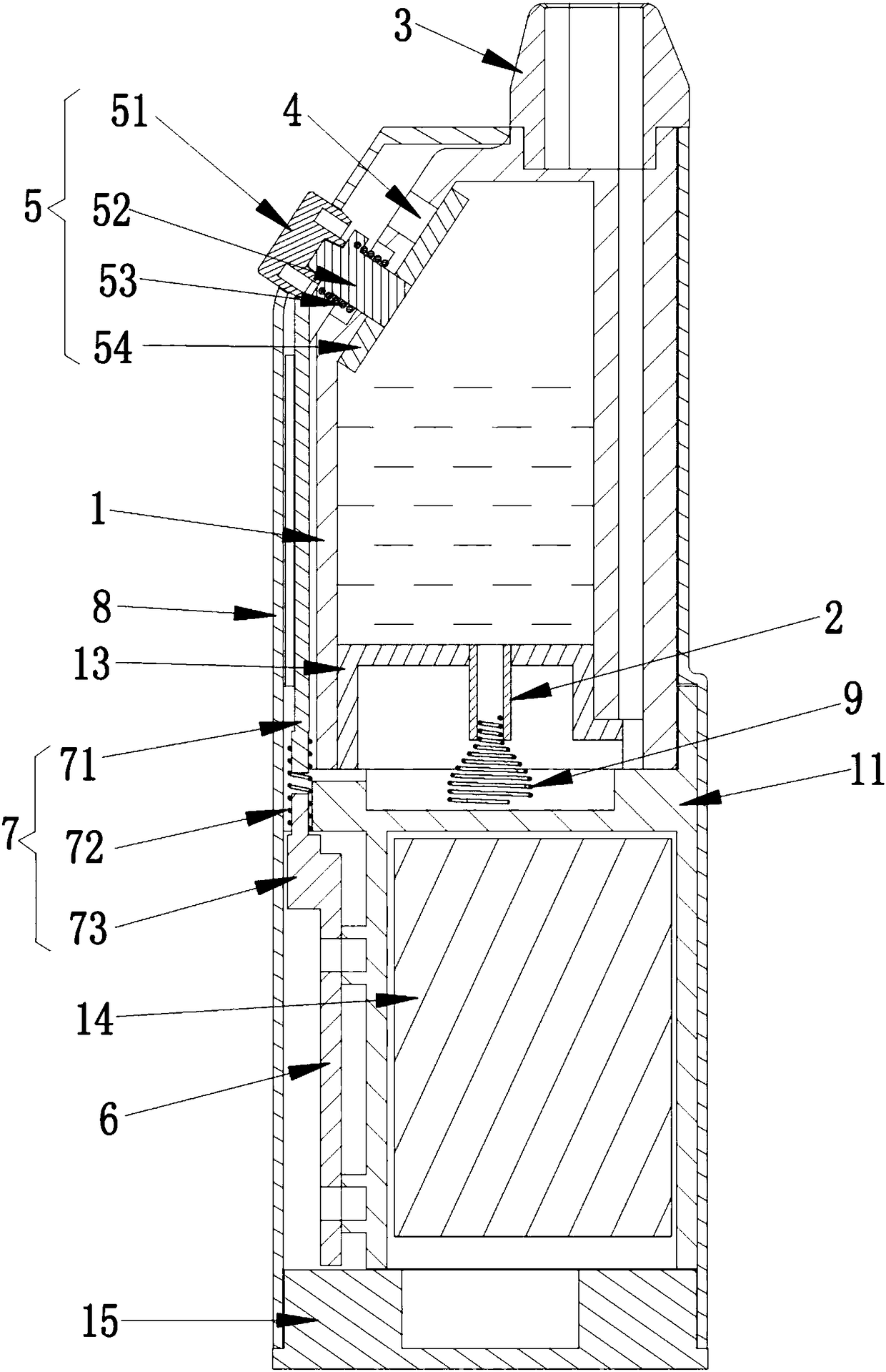
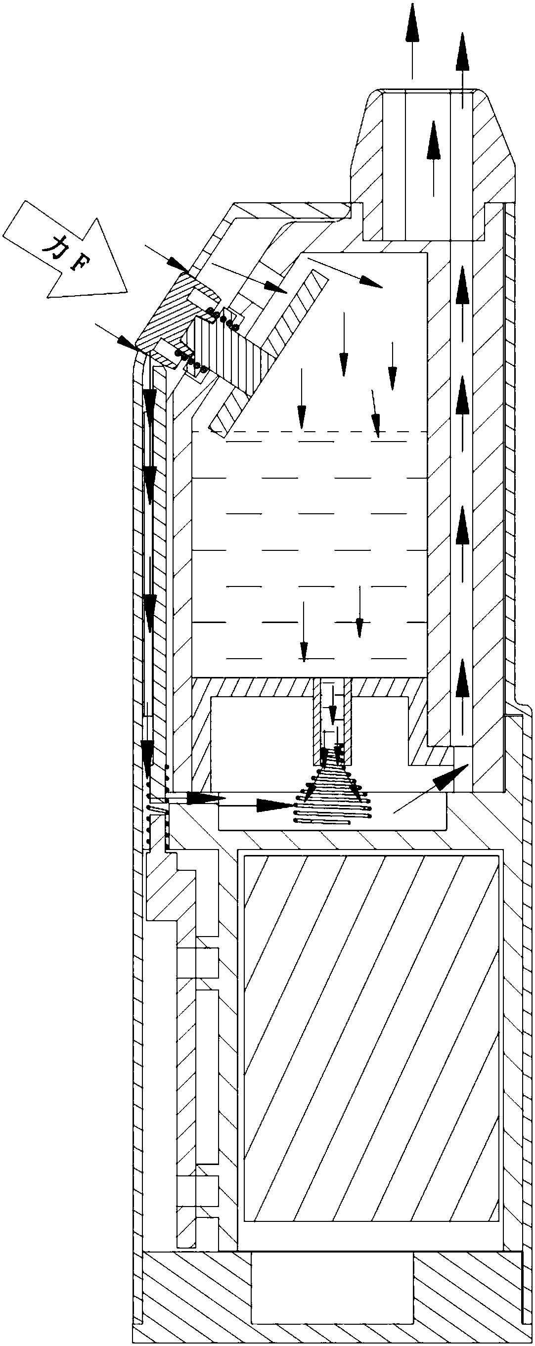
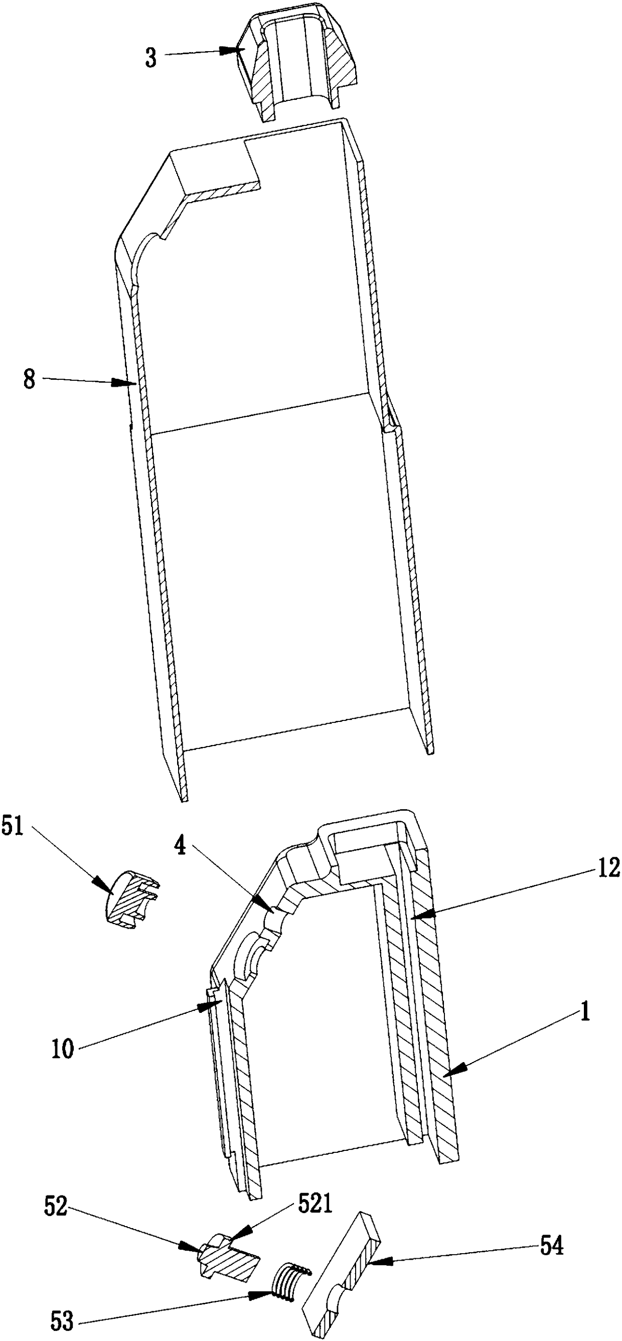
[0040] Such as Figure 1 to Figure 6 As shown, the electronic cigarette vaporizer includes an oil tank 1, a capillary tube 2 and a suction nozzle 3. The oil inlet end of the capillary tube 2 communicates with the inner cavity of the oil tank 1, and the oil outlet end of the capillary tube 2 communicates with the suction nozzle 3. The oil tank 1 is provided with a vent hole 4 that communicates the inner cavity of the oil tank 1 with the atmosphere, and also includes a button assembly 5 that can open or close the vent hole 4 . The inner diameter of the capillary 2 is 0.3-1.5 mm, preferably 0.5-0.8 mm.

[0041] The electronic cigarette atomizer also includes a circuit board 6 and a circuit switch assembly 7 for controlling whether the circuit key switch 73 on the circuit board 6 is connected; When it is turned on, the circuit switch assembly 7 controls the circuit key switch 73 to turn on; when the key assembly 5 controls the vent hole 4 to close, the circuit switch assembly 7 c...

Embodiment 2

[0056] The heating assembly 2 in Embodiment 1 and Embodiment 2 can also be replaced by Figure 8 The heating component 2 shown in the figure, in this embodiment, the heating component 9 includes a smoke oil guide part 91 extending into the oil outlet end of the capillary tube 2, a heating part 92 opposite to the outer end surface of the oil outlet end of the capillary tube 2, and the smoke oil guide part The heating part 91 is connected to the heating part 92; the heating component 9 is provided with an air passage 93 connecting the oil outlet end of the capillary 2 and the suction nozzle 3.

[0057] The heating part 92 is a cylindrical spring-type heating wire, and the e-liquid guiding part 91 includes a plurality of guide columns whose ends are fixedly connected to the heating component 9 , and the guiding columns are perpendicular to the axis of the heating part 92 .

[0058] The oil tank 1, the capillary 2, and the heating element 9 are arranged sequentially from top to ...


PUM


Abstract

The invention discloses an electronic cigarette atomizer, which comprises an oil bin, a capillary tube and a suction nozzle. The oil inlet end of the capillary tube is communicated with the oil bin inner cavity, and the oil outlet end of the capillary tube is communicated with the suction nozzle. The oil bin is provided with an air vent which communicates the oil bin inner cavity and the atmosphere, and also comprises a key assembly which can open or close the air vent. A circuit board and a circuit switch assembly for controlling whether a circuit key switch on the circuit board is turned onare also included. The key assembly and the circuit switch assembly are linked, and when the key assembly controls the air vent to open, the circuit switch assembly controls the circuit key switch toturn on; when the key assembly controls the vent to close, the circuit switch assembly controls the key switch to open. As that smoke oil can be quickly and timely supply to the heating component through the capillary tube for atomization, the us is not easy to suck large droplets, the atomization is sufficient, the smoke particles are fine and exquisite, the smoke mouthfeel is good, the smoke amount is large, the oral cavity is not scalded, and the user experience is good.

Description

technical field [0001] The invention belongs to the technical field of electronic cigarettes, and in particular relates to an electronic cigarette vaporizer. Background technique [0002] An existing electronic vaporizer utilizing a capillary to conduct oil includes a capillary, an oil tank, a suction nozzle and an air inlet, wherein one end of the capillary communicates with the inner cavity of the oil tank, and the other end of the capillary communicates with the suction nozzle. Existing capillaries are all made of exothermic materials. One end of the capillary sucks the e-liquid in the oil tank into the capillary, and the capillary heats the e-liquid in the capillary through self-heating, and the smoke generated by heating the e-liquid is ejected from the other end of the capillary, and the airflow enters from the air inlet, bringing the smoke to the suction The mouth is for the user to inhale. [0003] Existing electronic vaporizers utilizing capillary oil conduction h...

Claims


Application Information

Patent Timeline
Patent Type & Authority Applications(China)
IPC IPC(8): A24F47/00
CPCA24F47/008
Inventor 刘建福陈超英郭小义代远刚尹新强沈轶陈超高丽娜周永权
Owner CHINA TOBACCO HUNAN INDAL CORP
Why Eureka
Try Eureka