12/14 bearingless permanent magnet biased switched reluctance motor

A switched reluctance motor and permanent magnet bias technology, which is applied in the direction of magnetic attraction or thrust holding devices, electromechanical devices, electrical components, etc., can solve the problems of unstable magnetic field of the motor, large copper consumption of the motor, and increased cost.

Inactive Publication Date: 2014-04-09
BEIHANG UNIV
View PDF7 Cites 25 Cited by
  • Summary
  • Abstract
  • Description
  • Claims
  • Application Information

AI Technical Summary

Problems solved by technology

The current bearingless switched reluctance motor usually fixes the torque winding coil and the levitation force winding coil on a stator tooth, so there is a strong coupling between the two windings, making the internal magnetic field of the motor unstable, and it is difficult to achieve stable control of the motor levitation
However, the existing bearingless switched reluctance motor in which the torque winding and the suspension winding are fixed separately adopts a double winding structure on the stator suspension core, so the motor has the disadvantages of large copper consumption and high motor loss.
In the permanent magnet bias bearingless switched reluctance motor proposed in patent 201110246900.0, although it has a single winding structure, since the bias magnetic field in the motor starts from the N pole of the permanent magnet, it passes through the back yoke of the stator at one end and the levitation force of the stator Iron core, air gap, rotor core, rotor core from the shaft to the other end, air gap, stator core, stator back yoke back to the permanent magnet S pole, the permanent magnet needs to be placed between the two stator back yokes, so the motor needs Two sets of stator back yokes, stator torque cores, stator suspension force cores, and rotor cores are used to form a two-stage structure to place permanent magnets. Although it effectively provides a bias magnetic field, it greatly increases the axial length and increases the cost, making assembly more complex

Method used


Image

  • 12/14 bearingless permanent magnet biased switched reluctance motor
  • 12/14 bearingless permanent magnet biased switched reluctance motor
  • 12/14 bearingless permanent magnet biased switched reluctance motor

Examples


Embodiment Construction

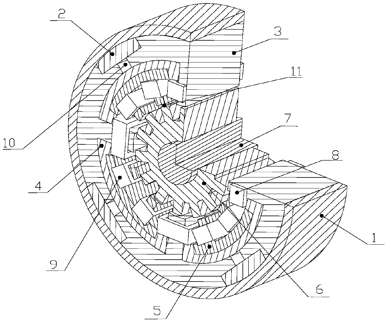
[0013] Such as figure 1 As shown, it is an axial sectional view of a 12 / 14 bearingless permanent magnet bias switched reluctance motor of the present invention, which consists of a stator back yoke 1, four permanent magnets 2, four stator suspension force cores 3, and four Magnetic isolation sleeve 4, four stator torque cores 5, one rotor core 6, one shaft 7, four suspension force winding coils 8, and eight torque winding coils 9. The stator suspension force core 3 places four stator suspension force core teeth along the +x, -x, +y, -y directions, and the suspension force winding coil 8 is wound on it; the stator torque core 5 has eight teeth in total, uniform Distributed on the circumference, and the torque winding coil 9 is wound thereon. The four permanent magnets 2 are respectively located in the slots of the stator levitation force core 3 near the stator back yoke 1 , that is, embedded between the stator levitation force core 3 and the stator back yoke 1 . The stator b...


PUM


Abstract

A 12/14 bearingless permanent magnet biased switched reluctance motor is formed by a stator back yoke, permanent magnets, stator suspension force iron cores, magnetism isolation sleeves, stator torque iron cores, a rotor iron core, suspension force winding coils, torque winding coils and a shaft. The inner side of the stator back yoke is provided with the stator suspension force iron cores; the permanent magnets are embedded between the stator back yoke and the stator suspension force iron cores; the magnetism isolation sleeves are arranged between the stator suspension force iron cores and the stator torque iron cores; the stator suspension force iron cores and the stator torque iron cores are wound with the suspension force winding coils and the torque winding coils respectively; and the stator suspension force iron cores and the stator torque iron cores are internally provided with the rotor iron core, and the rotor iron core is internally provided with the shaft. The permanent magnets provide a bias magnetic field, so that motor loss is reduced and axial length is reduced; meanwhile, through the adjustment of the positions of stator torque iron core teeth, electromagnetic torque of the motor is increased, and torque pulsation is reduced; and the defects of an original 12/14 bearingless switched reluctance motor are totally overcome from two aspects, and the efficiency of the motor is improved.

Description

technical field [0001] The invention relates to a 12 / 14 bearingless switched reluctance motor, in particular to a permanent magnet bias bearingless switched reluctance motor, which can be used as a high-speed, high-precision driving motor. Background technique [0002] With the rapid development of national industry, the development of high-speed and high-precision motors has been paid more and more attention. However, problems such as reliability and high loss restrict the development of high-speed and high-precision motors. Therefore, developing a motor with high reliability and low loss has become an urgent need in industrial technology. However, the traditional mechanical bearing motor has the disadvantages of large friction loss and short life of the motor. Although the existing air-floating and liquid-floating bearings solve various problems caused by friction, their application range is restricted due to their complex structure, low efficiency, and poor reliability. ...

Claims


Application Information

Patent Timeline
Patent Type & Authority Applications(China)
IPC IPC(8): H02N15/00H02K16/00
Inventor 王惠军薛秉坤鲍军芳刘剑峰
Owner BEIHANG UNIV
Why Eureka
Try Eureka