
Method and device in surveillance camera

A camera and image data technology, applied in the field of surveillance cameras, can solve problems such as inability to achieve, and achieve the effect of optimizing the amount of image processing

Active Publication Date: 2016-09-07
AXIS
View PDF4 Cites 0 Cited by
  • Summary
  • Abstract
  • Description
  • Claims
  • Application Information

AI Technical Summary

Problems solved by technology

However, when something happens, expect to be able to use high action, but with low level of PoE, maybe not possible

Method used


Image

  • Method and device in surveillance camera
  • Method and device in surveillance camera
  • Method and device in surveillance camera

Examples


Embodiment Construction

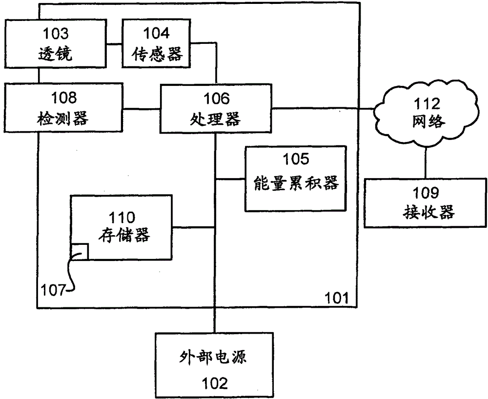
[0024] figure 1 A block diagram of an embodiment according to the invention is shown. The surveillance camera 101 is adapted to monitor the scene, not shown in the figure. As mentioned in the background, the surveillance camera 101 is either a permanent surveillance camera or installed on a temporary base.

[0025] The camera 101 may be any suitable digital camera capable of generating and transmitting video sequences or other types of image data, such as images and video metadata, over the network 112 to any entity connected to the network, such as image data receiving device 109. The camera 101 comprises a lens system 103 for collecting the incident light, an image sensor 104, for example in the form of a charge-coupled device CCD, a CMOS-sensor or similar, for registering the incident light, and circuits known in the art. For example, the circuitry typically includes image processing circuitry including an image / video encoder (implemented in hardware, software or any com...


PUM


Abstract

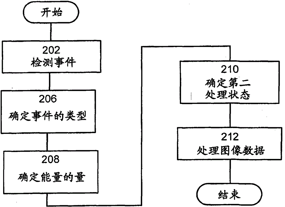
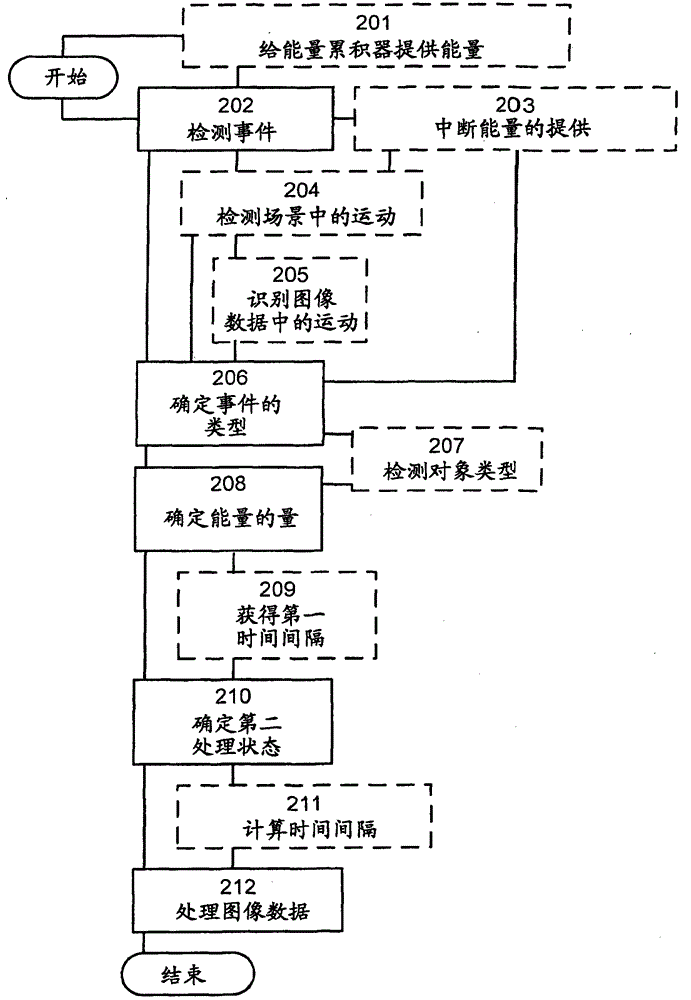
The invention relates to methods and devices in surveillance cameras. Surveillance cameras are connected to an external power source. The external power supply has an external maximum power level. Image data is processed in a first processing state. A surveillance camera detects (202) an event and determines (206) the type of event detected. An amount of energy for an energy accumulator in the surveillance camera is determined (208). A second processing state is determined (210) based on the event type and based on the external maximum power level and based on the determined amount of energy of the energy accumulator. This second processing state requires a power level higher than the external maximum power level. The image data is then processed (212) in a second processing state.

Description

technical field [0001] Embodiments herein relate generally to surveillance cameras and methods thereof. More specifically, it relates to saving power in surveillance cameras. Background technique [0002] Currently, surveillance cameras are installed in many places. Surveillance cameras are installed indoors and outdoors as well as permanent or temporary installations. Depending on where a surveillance camera is installed and depending on the conditions under which it will operate, the image processing capabilities required for a camera can vary widely. For example, surveillance of a position where images of many passing objects are processed during the day requires a lot of image processing power. The opposite situation is the monitoring of the same location at night when there is no target passing within the camera's field of view. In addition, due to the fact that image detectors / sensors are becoming more sophisticated and transmitting ever increasing streams of image...

Claims


Application Information

Patent Timeline
Patent Type & Authority Patents(China)
IPC IPC(8): H04N7/18H04N5/14
CPCG06F1/266G06F1/263G06F1/325G06F1/3287Y02D10/00H04N23/65H04N23/611H04N7/18
Inventor P·坎那马克A·尼尔逊
Owner AXIS
Learn More