
Exhaust cone for aircraft turbojet engine

A technology of turbojet and exhaust cone, applied in the direction of engine function, engine manufacturing, machine/engine, etc., can solve the problems of affecting the quality of components, high manufacturing cost, complex structure, etc.

Inactive Publication Date: 2014-04-09
AIRCELLE
View PDF6 Cites 3 Cited by
  • Summary
  • Abstract
  • Description
  • Claims
  • Application Information

AI Technical Summary

Problems solved by technology

[0017] According to the previous description, it can be known that the exhaust cone of the prior art ( figure 2 ) has a complex structure, including many parts, high manufacturing costs, and affects the quality of components, which cannot meet the needs

Method used


Image

  • Exhaust cone for aircraft turbojet engine
  • Exhaust cone for aircraft turbojet engine
  • Exhaust cone for aircraft turbojet engine

Examples


Embodiment Construction

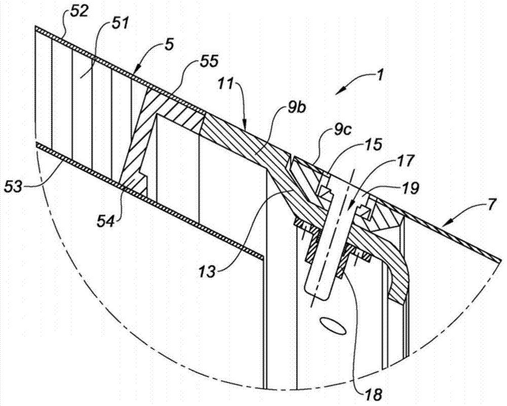
[0038] as in figure 2 shows more precisely that the front part 5 of the exhaust cone 1 is equipped with a sound-absorbing structure comprising a porous core 51, for example a honeycomb structure, formed by a perforated outer skin 52 and a solid inner skin 53. cover.

[0039] As previously described and according to the prior art, the porous core is closed by a C-shaped closure 54 also covered by an extension 55 of the outer skin 52 and by an extension of the inner skin 53 which extends Portion 55 is unperforated.

[0040] The connection between the sound-absorbing structure and the rear connecting flange 9b is provided by a C-shaped closure 54, as already explained, in particular by soldering the connection between these parts.

[0041] The flange 9b has a thickness ensuring that there is no offset (gap) from the outer skin 52 and its extension 55 in order to best provide the external aerodynamic continuity of the front cone part 5 .

[0042] Similarly, in the front part, ...


PUM


Abstract

The present invention relates to an exhaust cone for an aircraft turbojet engine comprising a front part having a front end fitted with a connecting flange (9a) for connection to a turbojet engine outlet and / or a rear end fitted with a connecting flange (9b) for connection to a rear part of the exhaust cone, said front part also being equipped with at least one noise attenuation structure comprising a corresponding external skin (52), characterized in that the external skin straddles at least part of the corresponding upstream or downstream connecting flange and is assembled therewith.

Description

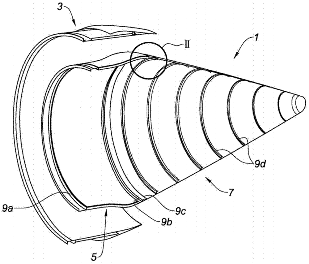
technical field [0001] The invention relates to an exhaust cone of an aircraft turbojet engine. Background technique [0002] As far as known technology is concerned, a suitable exhaust cone / main nozzle assembly is usually provided at the rear of the aircraft turbojet engine, so as to optimize, on the one hand, the flow of hot air exhausted by the turbojet engine and, on the other hand, to absorb at least part of the The noise produced by the interaction of these hot gases with the surrounding air and the cold air flow expelled by the fan of the turbojet engine. [0003] These elements are commonly referred to as the "cone" and "nozzle" or "primary nozzle". [0004] in the attached figure 1 One such conventional exhaust cone 1 is shown in , with its front and rear structures on the left and right sides of the figure, along the engine axis, respectively. [0005] Said exhaust cone is positioned downstream of the turbine of the turbojet engine on which the main nozzle is ar...

Claims


Application Information

Patent Timeline
IPC IPC(8): F02K1/82F02K1/04F02K1/44F02K1/80
CPCY02T50/671F02K1/827F02K1/04F05D2250/283F02K1/44F02K1/80F05D2230/232F05D2260/30Y02T50/60
Inventor 海伦·马洛菲利普·比安弗尼
Owner AIRCELLE
Learn More