Once through fan
A cross-flow fan technology, applied in the field of cross-flow fans, can solve the problem of reaching the limit of large diameter, and achieve the effects of inhibiting peeling, inhibiting deterioration and noise, and eliminating steps
- Summary
- Abstract
- Description
- Claims
- Application Information
AI Technical Summary
Problems solved by technology
Method used
Image

Examples
Embodiment approach 1
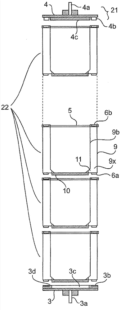
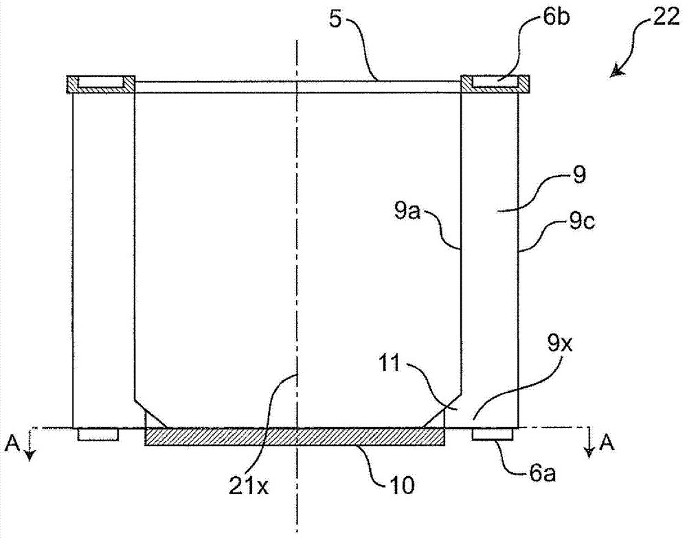
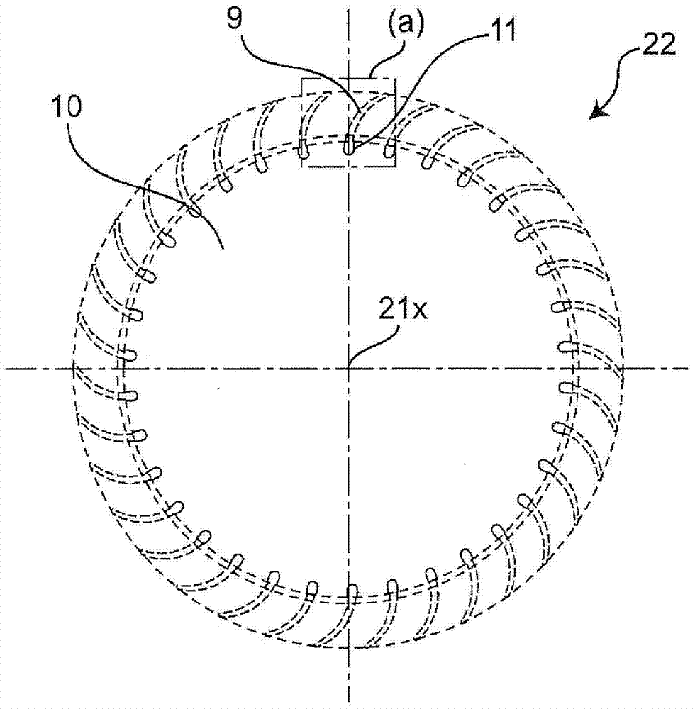
[0060] figure 1 It is an exploded cross-sectional view of the cross-flow fan according to Embodiment 1 of the present invention. figure 2 It is a cross-sectional view showing one impeller of the cross-flow fan according to the first embodiment. image 3 yes figure 2 The A-A line cross-sectional view of the cross-flow fan. Figure 4 It is a cross-sectional view of main parts showing the connecting parts of blades, protrusions, and reinforcement plates in the impeller according to the first embodiment. Figure 5 yes Figure 4 The B-B cross-sectional view of the connecting part of . In addition, for the prior art literature ( Figure 7 ~ Figure 12 ) The same structural components of the cross-flow fan are marked with the same symbols, and descriptions are omitted.
[0061] exist Figure 1 to Figure 5 Among them, the cross-flow fan 21 has an impeller 22 in which a plurality of blades 9 are arranged in an axial (rotation shaft 21 x ) direction and is connected in a cylind...
Embodiment approach 2
[0076] Image 6 It is a figure which shows the main part of the impeller 32 with which the cross-flow fan 31 which concerns on Embodiment 2 of this invention is equipped. In addition, the same code|symbol is attached|subjected to the same component as cross-flow fan 21 of Embodiment 1 mentioned above, and description is abbreviate|omitted.
[0077] Such as Image 6 As shown, the protruding length ( Image 6 The length in the left-right direction) is formed so as to gradually become smaller as it moves away from the reinforcing plate 10 in the axial direction. The axial height h of the impeller 32 of the protrusion 13 ( Image 6 The length in the vertical direction) is set within the range of 1% to 15% of the axial height H of the blade 9 (impeller 32 ) (that is, h / H=1% to 15%).
[0078] By setting the shape of the protruding portion 13 with respect to the entire impeller 32 in this way, sufficient strength for connecting the reinforcing plate 10 and the blade 9 can be ensu...
PUM
 Abstract
Description
Claims
Application Information
 - R&D
- Intellectual Property
- Life Sciences
- Materials
- Tech Scout
- Unparalleled Data Quality
- Higher Quality Content
- 60% Fewer Hallucinations
Browse by: Latest US Patents, China's latest patents, Technical Efficacy Thesaurus, Application Domain, Technology Topic, Popular Technical Reports.
© 2025 PatSnap. All rights reserved.Legal|Privacy policy|Modern Slavery Act Transparency Statement|Sitemap|About US| Contact US: help@patsnap.com