
Rear welding head of machine for welding edges of two sides of electronic element

A technology of electronic components and welding machines, which is applied in welding equipment, auxiliary welding equipment, welding/cutting auxiliary equipment, etc., can solve the problem that the assembly of small parts is not easy for manual assembly, the requirements for workers' proficiency are relatively high, and the quality and efficiency can be improved. Insufficient security and other issues, to achieve the effect of saving labor, reducing production costs, improving production efficiency and product yield

Inactive Publication Date: 2014-04-16
SUZHOU CHANG FEI AUTOMATION EQUIP FACTORY
View PDF11 Cites 0 Cited by
  • Summary
  • Abstract
  • Description
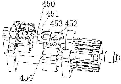
  • Claims
  • Application Information

AI Technical Summary

Problems solved by technology

[0002] In modern industrial manufacturing, many complex machines are assembled manually, including mobile phones and computers in the electronics industry, as well as automobile manufacturing and other household appliances; these industrial manufacturing requires a lot of small assembly Links are assembled together. For example, most electronic components in the electronics industry are assembled by machines. They were assembled manually in the past. Due to human factors, there will be deviations and efficiency problems in assembly, which will affect the overall production capacity and output value. Among them, the assembly of small parts is very difficult for manual assembly, which requires relatively high proficiency of workers, and it is easy to affect the quality of products, and some special electronic components also need some special processes such as welding. Such electronic It is certain that there will be problems when the components are completed manually, and the quality and efficiency cannot be guaranteed.

Method used


Image

  • Rear welding head of machine for welding edges of two sides of electronic element

Examples


Embodiment Construction

[0007] The preferred embodiments of the present invention will be described in detail below in conjunction with the accompanying drawings, so that the advantages and features of the invention can be more easily understood by those skilled in the art, so as to define the protection scope of the present invention more clearly.

[0008] see figure 1 , the embodiment of the present invention includes:

[0009] A rear welding head of a double-side leg welding machine for electronic components, the rear welding head of the double-side leg welding machine for electronic components includes a welding needle 450, a non-metallic welding needle holder 451, a welding needle support block 452, and an angle adjustment Rod 453 and adjustment screw 454, the welding needle 450 is inserted into the non-metallic welding needle holder 451, the rear side of the non-metallic welding needle holder 451 is provided with an angle adjustment rod 453, and the non-metallic welding needle holder 451 passes...


PUM


Abstract

The invention discloses a rear welding head of a machine for welding the edges of the two sides of an electronic element. The rear welding head of the machine for welding the edges of the two sides of the electronic element comprises welding needles, a nonmetal welding needle base, a welding needle support block, an angle adjustment bar and an adjustment screw, wherein the welding needles are arranged on the nonmetal welding needle base, the angle adjustment bar is arranged on the rear side of the nonmetal welding needle base, the nonmetal welding needle base is installed on the welding needle support block through the angle adjustment bar, the welding needle support block is L-shaped, and the adjustment screw used for adjusting the levelness of the welding needles is arranged on the side face of the welding support block. By the adoption of the rear welding head of the machine for welding the edges of the two sides of the electronic element, labor can be saved, production efficiency is improved, the rate of finished products is improved, the rejection rate of products is reduced, and production cost is reduced.

Description

technical field [0001] The invention relates to the field of mechanical manufacturing, in particular to a post-welding head of a double-side leg welding machine for electronic components. Background technique [0002] In modern industrial manufacturing, many complex machines are assembled manually, including mobile phones and computers in the electronics industry, as well as automobile manufacturing and other household appliances; these industrial manufacturing requires a lot of small assembly Links are assembled together. For example, most electronic components in the electronics industry are assembled by machines. They were assembled manually in the past. Due to human factors, there will be deviations and efficiency problems in assembly, which will affect the overall production capacity and output value. Among them, the assembly of small parts is very difficult for manual assembly, which requires relatively high proficiency of workers, and it is easy to affect the quality ...

Claims


Application Information

Patent Timeline
IPC IPC(8): B23K37/02
CPCB23K37/00
Inventor 陈飞彪
Owner SUZHOU CHANG FEI AUTOMATION EQUIP FACTORY
Learn More