Unlock instant, AI-driven research and patent intelligence for your innovation.

Automatic insertion machine

A technology of inserting machine and inserting plate, which is applied in the directions of metal processing mechanical parts, clamping and supporting, and can solve the problems of tool damage, damage and inability to use, collision of guiding mechanism, etc.

Active Publication Date: 2016-04-06
TCTM HONG KONG
View PDF5 Cites 1 Cited by
  • Summary
  • Abstract
  • Description
  • Claims
  • Application Information

AI Technical Summary

Problems solved by technology

[0002] Processing tools such as: milling cutters, drills, etc., must be inserted one by one on the insert plate after the production is completed, so as to prevent the processing tools from colliding during transportation, causing damage to the cutting edge of the processing tools and making them unusable. And the more precise machining tools, such as: micro-drills and micro-milling cutters, must be well protected. However, after the production of tools is completed, most tool manufacturers usually use a guiding mechanism to make the top of the tool face downward. Falling, during the falling process, make the handle of the tool face down and the edge of the knife face up, and then insert the handle into the insertion plate to form a positioning, but this method will collide with the guiding mechanism during the falling process of the tool , often causes damage to the tool, therefore, it is necessary to avoid damage to the tool due to collision during the inserting process

Method used


Image

  • Automatic insertion machine
  • Automatic insertion machine
  • Automatic insertion machine

Examples


Embodiment Construction

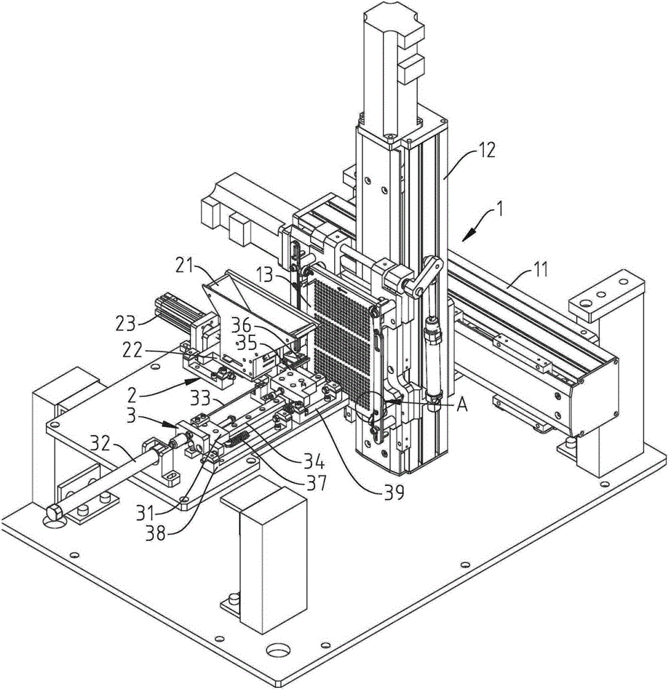
[0022] see Figure 1 to Figure 6 As shown, it can be clearly seen from the figure that the automatic disk insertion machine of the present invention is provided with a carrying device 1, a feeding device 2 and a pushing device 3, wherein:

[0023] The carrying device 1 is provided with a longitudinal displacer 11, a vertical displacer 12 is connected to the longitudinal displacer 11, and an insertion plate 13 is vertically connected to the vertical displacer 12, and a plurality of horizontal jacks are arranged on the surface of the insertion plate 13 131, so that the insertion plate 13 can be longitudinally and vertically displaced by the longitudinal displacement device 11 and the vertical displacement device 12.

[0024] The feeding device 2 is provided with a hopper 21, the hopper 21 is provided with a material placement space 211, and a material passage 212 is provided below the material placement space 211, and a plurality of forming knives 4 placed horizontally are stack...


PUM


Abstract

The invention discloses an automatic disk inserting machine. The automatic disk inserting machine is provided with a bearing device, a feeding device and a material pushing device. An insertion disk is vertically arranged on the bearing device. A plurality of transverse insertion holes are formed in the surface of the insertion disk. The feeding device is provided with a hopper with a plurality of stacked forming cutters. A feeding plate conveying the forming cutters is arranged below the hopper. The material pushing device is provided with a first base seat. A second driver is connected to one side of the first base seat. A thimble is arranged on one side of the first base seat. When the forming cutters are moved by the feeding plate to be just aligned to the thimble, the second driver pushes the first base seat to move transversely so as to enable the thimble to push the forming tools in a material moving tank, and the forming cutters are made to be transversely inserted into the insertion holes in the surface of the insertion disk. Consequently, the forming cutters are prevented from colliding to cause damage.

Description

technical field [0001] The invention relates to an automatic disc inserting machine, in particular to a disc inserting machine for inserting forming knives into the inserting discs one by one for positioning by means of automation. Background technique [0002] Processing tools such as: milling cutters, drills, etc., must be inserted one by one on the insert plate after the production is completed, so as to prevent the processing tools from colliding during transportation, causing damage to the cutting edge of the processing tools and making them unusable. And the more precise machining tools, such as: micro-drills and micro-milling cutters, must be well protected. However, after the production of tools is completed, most tool manufacturers usually use a guiding mechanism to make the top of the tool face downward. Falling, during the falling process, make the handle of the tool face down and the edge of the knife face up, and then insert the handle into the insertion plate t...

Claims


Application Information

Patent Timeline
Patent Type & Authority Patents(China)
IPC IPC(8): B23Q7/00
CPCB23Q3/15513B23Q3/157
Inventor 郑黄铮
Owner TCTM HONG KONG
Features
  • R&D
  • Intellectual Property
  • Life Sciences
  • Materials
  • Tech Scout
  • Unparalleled Data Quality
  • Higher Quality Content
  • 60% Fewer Hallucinations
Learn More