Power head structure of four-corner corner connecting machine

A corner forming machine and power head technology, applied in the direction of workpiece clamping devices, manufacturing tools, etc., can solve the problems of low efficiency, large size, and inability to transplant four-corner corners, etc., to improve accuracy and efficiency, and improve positioning accuracy Degree, beneficial effect Obvious effect

Active Publication Date: 2014-04-16
TAICANG WEGOMA MACHINERY
7 Cites 4 Cited by

AI-Extracted Technical Summary

Problems solved by technology

[0003] 1. The overall size is too large to be directly applied to the four-corner assembly line, otherwise, the processing range of the small size of the door frame cannot be met;
[0004] 2. The single-head corners are adjusted by the operator's hand and eye coordinatio...

Method used

During work, workpiece is placed on group corner head platen 3, concave positioning and side positioning mechanism adjust the outer angle of workpiece, wherein according to the size required, adjust the adjustment hand of the afterbody of reference concave positioning block 42 Wheel 48, said adjustment handwheel 48 is provided with digital display table 49, can improve the accuracy of calibration, start concave positioning feeding cylinder 47, drive concave positioning slide 41 to move forward along concave positioning guide rail 46 At the same time, it drives the auxiliary concave positioning block 43 located at the bottom of the concave positioning slide 41 to move forward, so that it corresponds to the position of the reference concave positioning block 42; at this time, the reference concave positioning block 42 and the auxiliary concave positioning block 43 At the same time, the upper and lower parts of the corner of the workpiece are positioned to improve the positioning accuracy. The left and right sides of the concave positioning structure are respectively equipped with side positioning columns A44 and side positioning columns B45, which are closely attached to the two outer sides of the workpiece Carry out positioning to improve positioning efficiency. The group corner knives A and group corner knives B, which are respectively arranged on both sides of the concave positioning and side positioning integra...

Abstract

The invention relates to a power head structure of a four-corner corner connecting machine. The power head structure of the four-corner corner connecting machine comprises a corner connecting head base plate, a corner connecting head table plate, a concave positioning and side positioning integrating mechanism, a convex positioning mechanism and a perpendicular compression mechanism, wherein equally high supporting plates are perpendicularly installed on the corner connecting head base plate, the corner connecting head table plate is arranged on the equally high supporting plates, the concave positioning and side positioning integrating mechanism is horizontally installed on the corner connecting head table plate, the perpendicular compression mechanism is installed above the concave positioning and side positioning integrating mechanism, and the convex positioning mechanism is perpendicularly installed on the corner connecting head table plate. By effectively integrating original concave positioning, side positioning, convex positioning and perpendicular positioning, the power head structure of the four-corner corner connecting machine improves the efficiency of positioning and adjusting four-corner doors and windows, and improves the yield rate.

Application Domain

Work holders

Technology Topic

EngineeringMechanical engineering +1

Image

  • Power head structure of four-corner corner connecting machine
  • Power head structure of four-corner corner connecting machine
  • Power head structure of four-corner corner connecting machine

Examples

  • Experimental program(1)

Example Embodiment

[0025] The present invention will be further clarified below in conjunction with the drawings and specific embodiments.
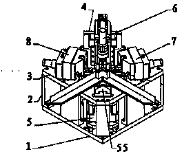
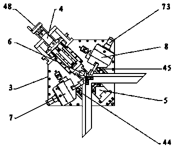
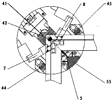
[0026] Such as Figure 1-5 As shown, a four-corner corner assembly machine power head structure includes a corner group base plate 1, a corner group head platen 3, a concave positioning and side positioning integrated mechanism 4, a convex positioning mechanism 5, and a vertical pressing mechanism 6. The corner assembly base plate 1 is vertically installed with a contour support plate 2, the corner assembly plate 3 is arranged on the contour support plate 2, and the concave positioning and side positioning integrated mechanism 4 is installed horizontally. On the corner assembly plate 3, the vertical pressing mechanism 6 is installed above the concave positioning and side positioning integrated mechanism 4; the convex positioning mechanism 5 is vertically installed on the corner assembly base plate 1.
[0027] The concave positioning and side positioning integrated mechanism 4 includes a concave positioning slide 41, a reference concave positioning block 42, an auxiliary concave positioning block 43, a side positioning column A44, and a side positioning column B45. The positioning block 42 is horizontally installed on the corner assembly table 3, the reference concave positioning block 42 is provided with a concave positioning guide 46, and the concave positioning sliding seat 41 is provided on the concave positioning guide 46. The lower part of the concave positioning slide 41 is provided with an auxiliary concave positioning block 43, and the rear end of the concave positioning slide 41 is provided with an auxiliary concave positioning feed cylinder 47; the side positioning column A44 and the side positioning column B45 are separately arranged in the reference concave -Shaped positioning block 42 on both sides; the reference concave positioning block 42 is provided with an adjusting hand wheel 48 on the tail, and the adjusting hand wheel 48 is provided with a digital display table 49; the concave positioning and side positioning integrated mechanism 4 Both sides are provided with a group corner knife A and a group corner knife B respectively. The group corner knife A and the group corner knife B are respectively connected to the group corner cylinder A and the group corner cylinder B. The group corner cylinder A, The angle forming cylinder B is fixedly installed on the forming angle platen; the end of the forming angle forming cylinder A and the forming angle forming cylinder B are equipped with cylinder adjusting handles.
[0028] The convex positioning mechanism 5 includes a convex positioning support frame 51, a convex positioning linear guide 52, a convex positioning sliding block 53, a convex positioning mounting slide 54, a convex positioning block 55, and a convex positioning lifting cylinder. 56. The convex positioning lift guide shaft 57, the convex positioning linear guide 52 is installed on the base plate 1, the convex positioning slider 53 is provided on the convex positioning linear guide 52, and the convex positioning A convex positioning and supporting frame 51 is fixedly installed on the sliding block 53. The convex positioning and lifting guide shaft 57 is vertically installed at the bottom of the convex positioning and supporting frame 51. The convex positioning and mounting sliding seat 54 is arranged on the convex shape. Position the top of the lifting guide shaft 57, the tail of the convex positioning and mounting slide 54 is provided with a convex positioning lifting cylinder 56, and the upper part of the convex positioning and mounting slide 54 is provided with a convex positioning block 55. The positioning and supporting frame 51 is connected to a gas-liquid series cylinder 58, which is fixedly installed on the bottom plate 1 of the corner head; the tail end of the convex positioning linear guide 52 is equipped with a forming switch, the A hinged ear seat is provided on the bottom plate 1 of the corner head to support the gas-liquid tandem cylinder.
[0029] The vertical pressing mechanism 6 includes a vertical pressing cylinder 62, a vertical pressing and retreating cylinder 61, the vertical pressing and retreating cylinder 61 is installed transversely on the upper part of the concave positioning slide 41, the vertical pressing cylinder 62 is longitudinally installed at the right end of the vertical compression retraction cylinder 61.
[0030] When working, the workpiece is placed on the corner assembly plate 3, and the concave positioning and side positioning mechanism adjusts the outer corner of the workpiece. The adjustment handwheel 48 at the tail of the reference concave positioning block 42 is adjusted according to the required size. The adjusting hand wheel 48 is provided with a digital display 49, which can improve the accuracy of calibration, activate the concave positioning and feeding cylinder 47, and drive the concave positioning slide 41 to move forward along the concave positioning guide 46 while driving The auxiliary concave positioning block 43 arranged at the lower part of the concave positioning slide 41 moves forward to make it correspond to the position of the reference concave positioning block 42; at this time, the reference concave positioning block 42 and the auxiliary concave positioning block 43 are aligned simultaneously The upper and lower parts of the workpiece corner are positioned to improve the accuracy of positioning. The left and right sides of the concave positioning structure are respectively provided with side positioning posts A44 and B45, which are closely attached to the two outer sides of the workpiece for positioning. The positioning efficiency is improved. The corner knives A and B, which are separately arranged on both sides of the concave positioning and side positioning integrated mechanism 4, are driven by the corner oil cylinder A and the corner oil cylinder B to tighten with the workpiece profile. The end of the angle group cylinder A and group angle cylinder B are equipped with cylinder adjustment handles; while the concave positioning and measurement are integrated structures to locate the outer corner of the workpiece, the convex positioning mechanism 5 positions the inside of the workpiece, Wherein, the convex positioning lift cylinder 56 is activated to prompt the convex positioning slide to move upward along the convex positioning lift guide shaft 57, and the gas-liquid series cylinder pushes the convex positioning support frame 51 to move along the convex positioning linear guide 52 to the specified position. , The convex positioning block 55 locates the inside of the workpiece, the concave positioning and side positioning integrated mechanism 4 and the convex positioning device cooperate to make the workpiece tightly connected laterally; the vertical pressing and retreating cylinder 61 acts to advance the vertical pressing cylinder 62 Right above the joint of the work piece, the vertical pressing cylinder 62 acts to press the work piece tightly and vertically. At this point, the precise positioning of the workpiece group angle is achieved.
[0031] When the angle grouping process is completed, each mechanism returns to the original position in reverse according to the above steps.
[0032] The embodiments are only to illustrate the technical concept and characteristics of the present invention, and their purpose is to enable those skilled in the art to understand the content of the present invention and implement them accordingly, and cannot limit the protection scope of the present invention. All equivalent changes or modifications made in accordance with the spirit of the present invention should be covered by the protection scope of the present invention.

PUM

no PUM

Description & Claims & Application Information

We can also present the details of the Description, Claims and Application information to help users get a comprehensive understanding of the technical details of the patent, such as background art, summary of invention, brief description of drawings, description of embodiments, and other original content. On the other hand, users can also determine the specific scope of protection of the technology through the list of claims; as well as understand the changes in the life cycle of the technology with the presentation of the patent timeline. Login to view more.

Similar technology patents

Large size mounting RFID upside-down mounting pasting method and apparatus thereof

InactiveCN102324393AImprove work efficiencysave sample time
Owner:广东宝丽华服装有限公司

Device for removing low-melting-point alloy from inner cavity of blade

ActiveCN106761953Ashort removal timeImprove work efficiency
Owner:CHINA HANGFA SOUTH IND CO LTD

Classification and recommendation of technical efficacy words

  • Improve work efficiency
  • Improve efficiency and precision

Cooperation service platform facing different source data

InactiveCN101174957AImprove management level and qualityImprove work efficiency
Owner:NANJING UNIV OF FINANCE & ECONOMICS

Screw drilling tool, vertical drilling tool testing method and well inclination simulation testing equipment

InactiveCN111594144AReduced height requirementsImprove work efficiency
Owner:DEZHOU UNITED GASOLINEEUM MACHINERY

Method for intelligent automatic identification of transmission circuit parts

Owner:INFORMATION COMM COMPANY STATE GRID SHANDONG ELECTRIC POWER +2

Keyboard spill-proofing mechanism

ActiveUS7030330B2minimize manufacturing costimprove work efficiency
Owner:LITE ON SINGAPORE PTE LTD

Novel point cloud parallel Softassign registering algorithm

InactiveCN104463826Aavoid local registrationImprove efficiency and precision
Owner:镇江福人网络科技有限公司

Operation system for puncture, control method and control device

ActiveCN111513849AImprove efficiency and precision
Owner:BOE TECH GRP CO LTD

CT image liver tumor segmentation method based on deep learning

PendingCN110570432AImprove efficiency and precision
Owner:BEIJING UNIV OF TECH

Lens laminating system and method

PendingCN109739006AReduce manual labor intensityImprove efficiency and precision
Owner:WUHAN RAYCUS FIBER LASER TECHNOLOGY CO LTD

Method, apparatus, server and data processing method for determining timeout duration

ActiveCN109144700AImprove efficiency and precisionThread calls are stable
Owner:ADVANCED NEW TECH CO LTD
Why Eureka
Try Eureka