
Biomass Feeding Device

A feeding device, biomass technology, applied in packaging, fuel supply, conveyor objects, etc., can solve the problems of poor sealing, entering the combustion device or gasification device, unable to achieve continuous feeding, etc., to avoid entanglement and accumulation. The effect of increasing density

Active Publication Date: 2016-02-03
山东知周环境科技有限公司
View PDF5 Cites 0 Cited by
  • Summary
  • Abstract
  • Description
  • Claims
  • Application Information

AI Technical Summary

Problems solved by technology

Biomass has the characteristics of loose structure, low bulk density, high fiber content, slender fibers, and mutual adhesion, which makes it easy to cause problems such as shed material and entanglement during the feeding process, which affects the continuous transportation of biomass and makes the gasification device and The airtightness between the feeding devices is poor, which affects the normal operation of the feeding devices
Poor sealing between the feed device and the gasification device will cause a series of problems: when the system is in negative pressure operation, it will cause air to enter the combustion device or gasification device through the feed device, affecting the interior of the combustion device or gasification device The overall smooth flow of the gasifier causes the gasifier to run in a direction deviated from the design. When the system is in positive pressure operation, the gas from the combustion device or the gasification device will escape through the feeding device, making it difficult for the material to enter the gasifier. In severe cases, it may cause fuel, fire
[0004] Due to factors such as loose biomass structure, low bulk density, high fiber content, slender fibers, and mutual adhesion of the existing gasification device feeding device, problems such as material shed and winding during the feeding process cannot be realized. Continuous feeding
This limits the application of biomass gasification to a large extent, and even the biomass gasification that cannot be realized normally

Method used


Image

  • Biomass Feeding Device
  • Biomass Feeding Device
  • Biomass Feeding Device

Examples


Embodiment Construction

[0026] The present invention will be described in further detail below in conjunction with the accompanying drawings and specific embodiments. The following is only exemplary and does not limit the protection scope of the present invention.

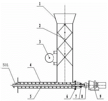
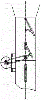
[0027] Reference attached figure 1 , 2 , 3, 4, a kind of biomass feeding device, comprises material cylinder 1, distributor and feeder; Distributor comprises distributing motor 3 and connecting rod mechanism 2, the output shaft of distributing motor 3 is connected transmission mechanism, and transmission mechanism is connected The linkage mechanism 2, the linkage mechanism is set in the barrel 1, the material distribution motor 3 drives the linkage mechanism 2 through the transmission mechanism to realize the material shifting and continuous feeding, and pushes the biomass into the feeder; the feeder includes a shell 4. The auger body 5 and the feed motor 9, the casing 4 and the barrel 1 are combined at right angles, and the casing 4 is ...


PUM


Abstract

The invention provides a biomass feeding device. By using the biomass feeding device, blockage of materials can be avoided, the application range of the materials is wide, and the materials can be fed continuously. The biomass feeding device comprises a barrel, a distributor and a feeder, wherein the distributor comprises a distributing motor and a connecting rod mechanism; an output shaft of the distributing motor is connected with a transmission mechanism; the transmission mechanism is connected with the connecting rod mechanism; the connecting rod mechanism is arranged in the barrel; the feeder comprises a shell, an auger and a feeding motor; the shell is combined with the barrel in a right-angled manner; the shell is positioned at the lower end of the barrel and is communicated with the inside of the barrel; one end of the auger is connected with the feeding motor; and the other end of the auger penetrates in the shell and outwards extends to form a retention section.

Description

technical field [0001] The invention relates to a feeding device, in particular to a biomass feeding device, which is suitable for feeding a combustion device or a gasification device. Background technique [0002] my country is extremely rich in biomass energy. Only agricultural biomass waste resources such as crop straws are 7×10⁸t / h, equivalent to 3.5×10⁸t standard coal, and forestry residues are about 1.5×10⁸t / h, equivalent to about 0.7×10⁸t standard coal. The utilization of biomass energy has achieved a balance between CO2 absorption and emission, and has strong competitiveness in meeting the more stringent decarbonization requirements in the future. Biomass gasification can convert low-grade energy into high-grade energy, and is the best choice for biomass energy utilization. At present, the furnace types used in domestic biomass gasification generally include fixed-bed gasifiers and fluidized-bed gasifiers. However, the fixed-bed gasifier has not been widely used du...

Claims


Application Information

Patent Timeline
Patent Type & Authority Patents(China)
IPC IPC(8): B65G47/18B65D88/64B65G33/24F23K3/00
Inventor 强宁刘兆远于杰霍燕初海石王晓昌董磊
Owner 山东知周环境科技有限公司
Learn More