Pot-type carbon calciner

A calcination furnace and carbon technology, applied in the field of calcination kilns, can solve the problems of low thermal efficiency and insufficient utilization of waste heat, etc., and achieve the effects of high automation, energy saving and labor intensity reduction

Active Publication Date: 2012-10-24
JINAN AOHAI CARBON PROD +1
View PDF5 Cites 6 Cited by
  • Summary
  • Abstract
  • Description
  • Claims
  • Application Information

AI Technical Summary

Problems solved by technology

[0003] In order to overcome the shortage of insufficient utilization of waste heat in existing calcinat...

Method used


Image

  • Pot-type carbon calciner
  • Pot-type carbon calciner

Examples


Embodiment 1

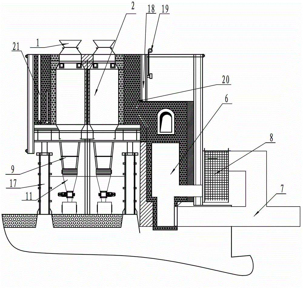
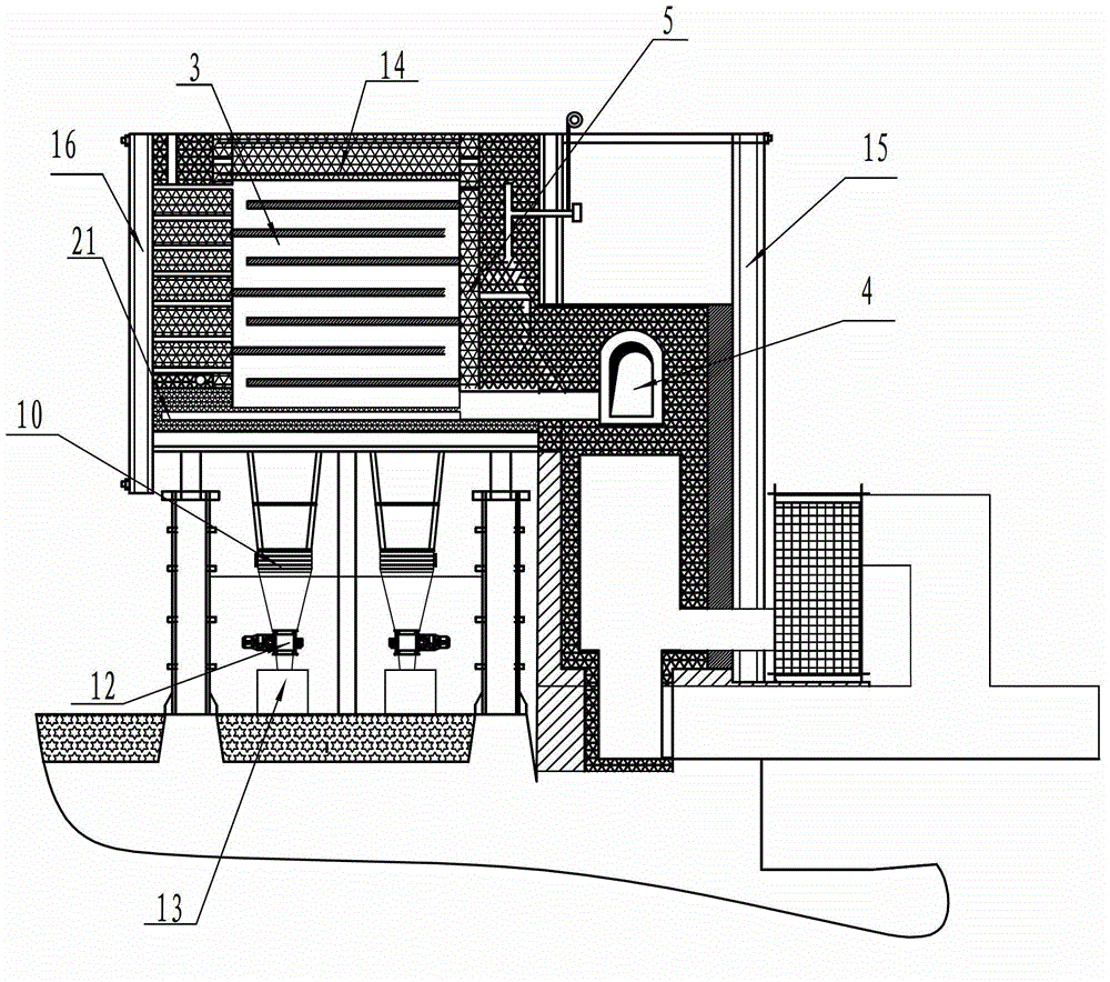
[0018] Embodiment 1, a tank-type carbon calcination furnace, every four calcination tanks 2 and furnace walls with heating channels on both sides of the tank form a combustion chamber, and there are expansion joints and collection flues 4 between each combustion chamber, There are 8-10 layers of fire channels 3 on the furnace wall with heating channels. The fire channels communicate with the preheating air channels. The calcination tank is connected to the discharge tank, and there is an interlayer cooling water jacket 9 on the periphery of the discharge tank. Its characteristics are: the entire The calciner is composed of 18 combustion chambers arranged in a line and a total of 72 calciner tanks. The length of the calciner tank is 2180mm, the width is 360mm, and the height is 5576mm. The front wall of the calcination furnace is equipped with a large tool holder 15 for protecting the furnace, and the rear wall is provided with a furnace protection frame 16. The bottom of the co...


PUM


Abstract

The invention discloses a pot-type carbon calciner and belongs to calciners for carbon production. One combustion chamber is formed by each four calcination pots and furnace walls with heating fire channels, the furnace walls with the heating fire channels are located on two sides of a pot body, expansion joints and smoke converging flues are arranged among the combustion chambers, each of the furnace walls with the heating fire channels has 8 to 10 layers of fire channels, the fire channels are communicated with a preheated air channel, the calcination pot body is connected with a material discharge pot, and an interlayer cooling water jacket is disposed on the periphery of the material discharge pot. The pot-type carbon calciner is characterized in that the entire calciner is formed by 18 combustion chambers which are linearly arranged and 72 calcination pots, a calciner protection large cutter frame is arranged outside the front wall of the calciner, a calciner protection frame is arranged outside the rear wall of the calciner, the bottoms of the combustion chambers are supported by supporting columns at the bottom of the calciner, a feed opening is disposed at the top of the calcination pot body, the material discharge pot is connected with the bottom of the calcination pot body, the interlayer cooling water jacket is disposed on the periphery of the material discharge pot, a material discharge device is installed at the lower end of the material discharge pot, and a small storage bin is mounted between the material discharge device and a discharge valve, so that volatile matter two-way utilization is achieved, the full-automatic closed type continuous discharging is achieved, and the pot-type carbon calciner has good economic and environmental benefits.

Description

technical field [0001] The invention belongs to a calcining kiln, in particular to a pot-type calcining furnace for carbon production. Background technique [0002] Tank calciner is a commonly used calcination equipment for carbon production. The material is isolated from the air in the tank for indirect heating and calcination to remove the volatile components in the carbon material. This calciner can make full use of the combustion of a large amount of volatiles released from the carbon material during calcination. Heat reduces energy consumption, but the existing tank-type calciner has shortcomings such as a small number of groups and insufficient air supply, resulting in insufficient use of waste heat, low calcining efficiency and quality. Contents of the invention [0003] In order to overcome the disadvantages of insufficient utilization of waste heat and low thermal efficiency of existing calcination furnaces, the present invention provides a pot-type carbon calcina...

Claims


Application Information

Patent Timeline
IPC IPC(8): C01B31/02C01B32/05
CPCY02P20/129
Inventor 赵敬利李西平董孟亮赵庆才董建翔崔岩翟美于磊于普生
Owner JINAN AOHAI CARBON PROD
Why Eureka
Try Eureka